Cutting tools

A technology of cutting tools and cutting knives, which is applied in the direction of manufacturing tools, metal sawing equipment, metal processing equipment, etc., can solve the problem of dust flying, and achieve the effect of preventing dust flying

Active Publication Date: 2014-01-29
MAKITA CORP
View PDF10 Cites 6 Cited by
  • Summary
  • Abstract
  • Description
  • Claims
  • Application Information

AI Technical Summary

Problems solved by technology

Therefore, there is a possibility that part of the dust discharged from the cutting part will fly backward through the gap between the rear end edge of the fixed cover and the dust cover.

Method used


Image

  • Cutting tools
  • Cutting tools
  • Cutting tools

Examples


Embodiment Construction

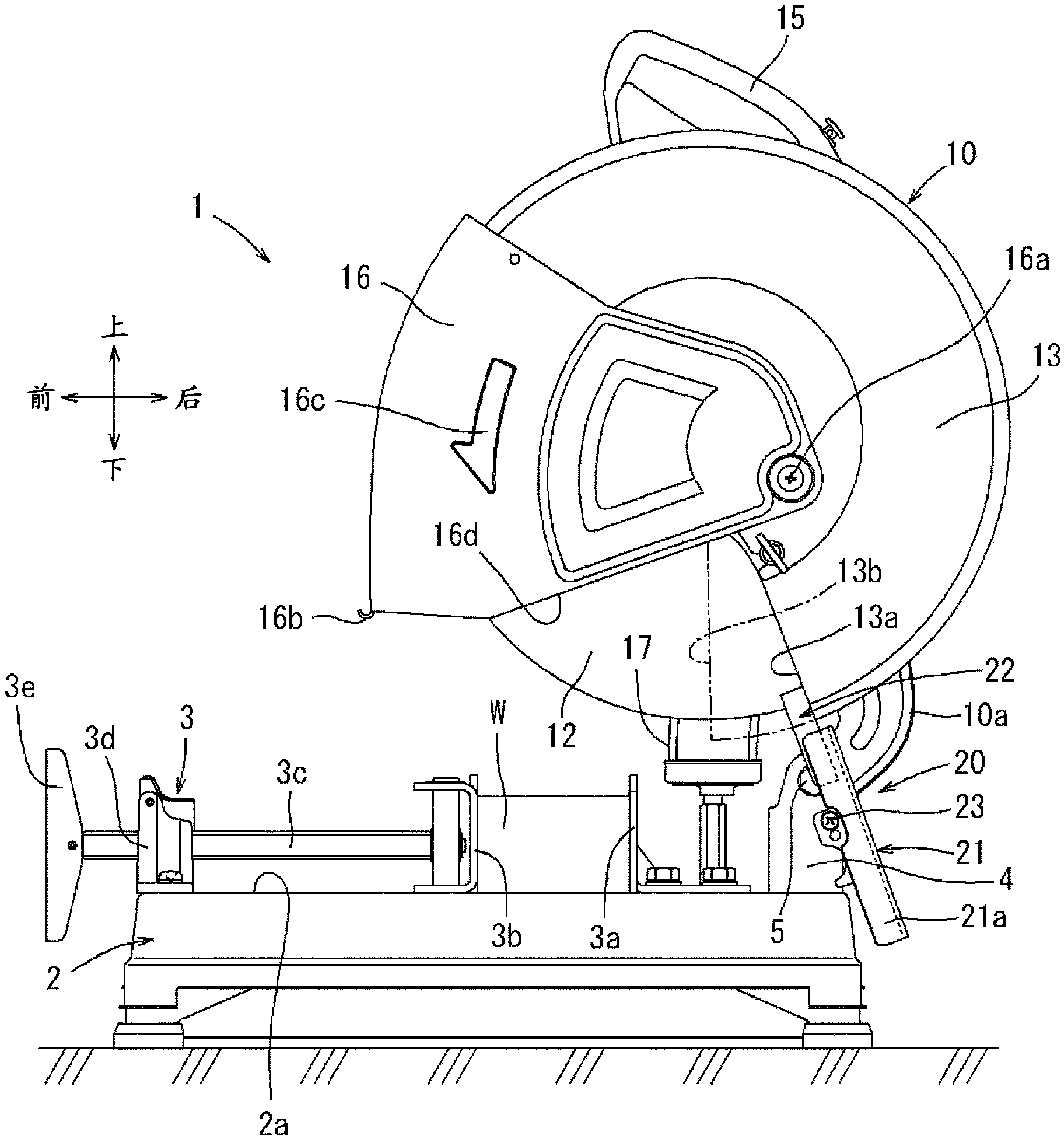
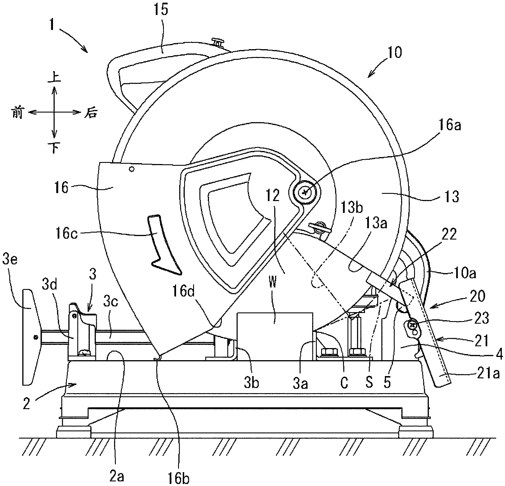
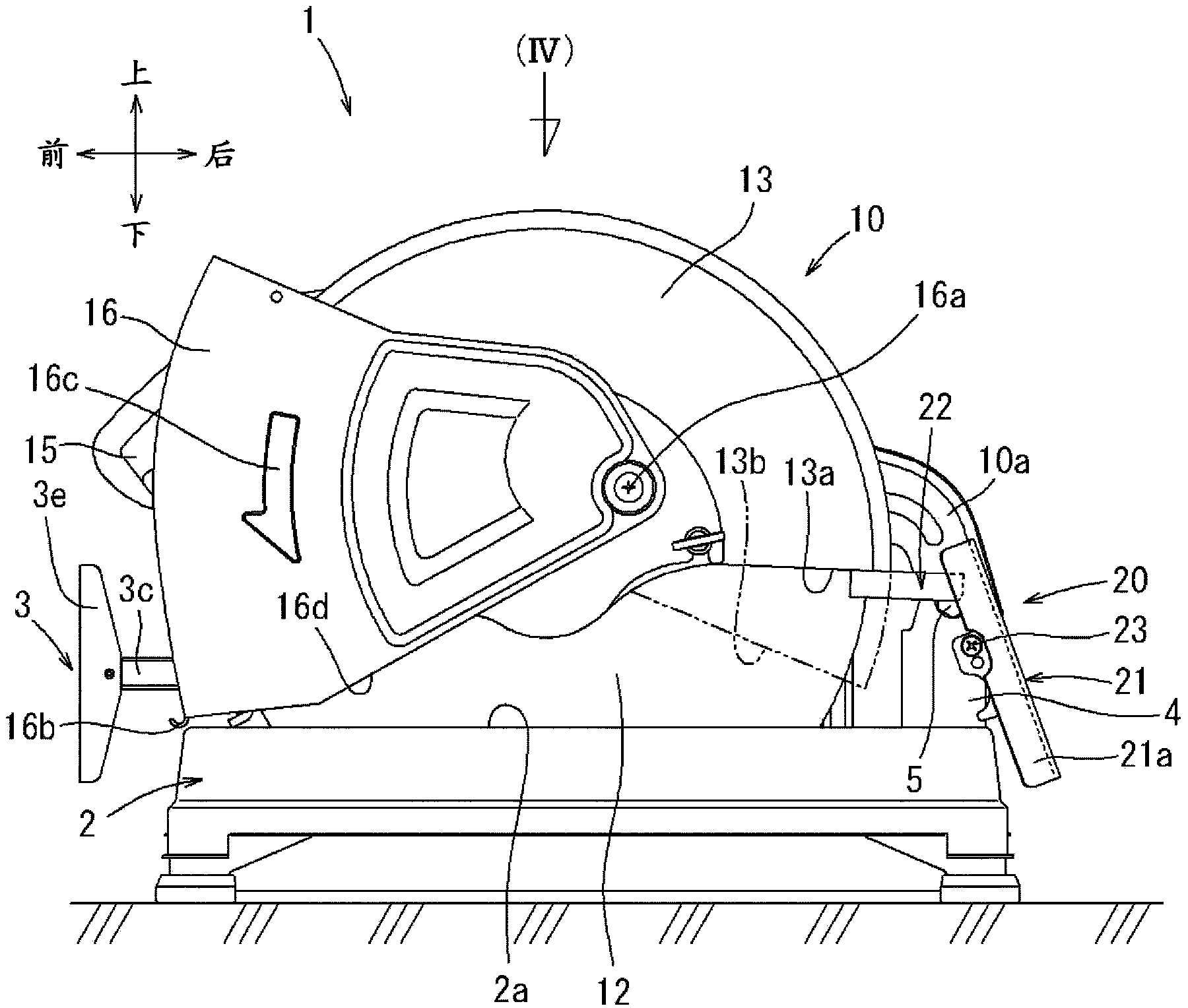
[0033] Refer below Figure 1 to Figure 8 Specific embodiments of the present invention will be described. figure 1 Shown is the cutting tool 1 according to this embodiment. The cutting tool 1 is a cutting machine for metal processing mainly used for cutting a workpiece W such as a metal material, and has a base 2 and a tool body 10, wherein the base 2 is used to place the workpiece W On; the tool body 10 is supported on the base 2 . exist figure 1 In , the operator operates the cutting tool 1 on the left side of the drawing. In the following description, regarding the front-rear direction of components and the like, the front side as seen from the operator (left side in the drawing) is defined as the front side, and the side away from the operator (right side in the drawing) is defined as the rear side. Additionally, if Figure 4 As shown, the left and right directions are directions based on the operator.

[0034]A clamp device 3 for fixing the workpiece W to be cut is ...


PUM


Abstract

A cutting tool (1) may include a base (2) having an upper surface (2a) for placing a workpiece (W) thereon, and a tool unit (10) vertically movably supported on the base (2). The tool unit (10) may include a rotary circular cutter (12) for cutting the workpiece (W) and a cover (13) configured to cover a part of the cutter (12). A chip guard (20) may be disposed between the base (2) and the cover (13) and configured to receive powder dust produced at a cut portion (C) of the cutter (12) and blown in a rearward direction from the cut portion (C). The chip guard (20) may extend along an entire vertical length of a space formed between the cover (13) and the upper surface (2a) of the base (2).

Description

technical field [0001] The present invention relates to a cutting tool for metal processing (Metal Cutting Chop Saw) for cutting a workpiece such as a metal pipe material. Background technique [0002] The following patent documents disclose technologies related to cutting tools for metal working. This cutting tool has a base (pedestal) and a tool body, wherein the base is used to be placed on the workpiece to be cut, the tool body is supported on the base in a manner that can rock (rotate) up and down, and the tool body has Cutting blades (round thin plate-shaped grinding wheels, saw blades for metal cutting) are driven and rotated by an electric motor as a driving source. The upper side of the cutting blade is covered by the fixed cover for approximately half the circumference. This fixed cover prevents cutting dust from flying around. [0003] In such a cutting tool, since sparks generated at the cutting site and cutting dust such as iron powder have high heat, it is n...

Claims


Application Information

Patent Timeline
Patent Type & Authority Applications(China)
IPC IPC(8): B23Q11/08
CPCB23D59/006B23D45/042Y10T83/7693
Inventor 松原功治
Owner MAKITA CORP
Why Eureka
Try Eureka