Vertical grain taking and die bonding mechanism and vertical die bonding machine using the same

A technology of solid crystal and wafer table, which is applied in semiconductor/solid-state device manufacturing, electrical components, circuits, etc., can solve the problems of long horizontal movement distance, long horizontal movement time, and low production efficiency, so as to prolong the service life and improve production Efficiency, the effect of reducing production costs

Pending Publication Date: 2017-06-20
SUZHOU ACCURACY ASSEMBLY AUTOMATION CO LTD
View PDF8 Cites 5 Cited by
  • Summary
  • Abstract
  • Description
  • Claims
  • Application Information

AI Technical Summary

Problems solved by technology

[0003] The main welding head of the existing crystal bonding machine moves along the horizontal circle of the wafer table on the top of the wafer table. Figure 5 , and for example, the Chinese patent application authorization announcement number is: CN203774253U, a kind of glue-covered die-bonding equipment, when taking crystal and solid crystal, such as figure 1 As shown, the swing arm 21 moves horizontally above the wafer table to complete the crystal extraction and die bonding operations, take out the die 22, and then place the die 22 on the substrate 23 after dispensing. However, due to the different sizes of the substrates, some substrates Larger size, after the welding head picks up the crystal, the horizontal movement distance is longer, which leads to a longer horizontal movement time when the welding head picks up the crystal and solidifies it, resulting in low production efficiency and high production costs

Method used


Image

  • Vertical grain taking and die bonding mechanism and vertical die bonding machine using the same
  • Vertical grain taking and die bonding mechanism and vertical die bonding machine using the same
  • Vertical grain taking and die bonding mechanism and vertical die bonding machine using the same

Examples


Embodiment Construction

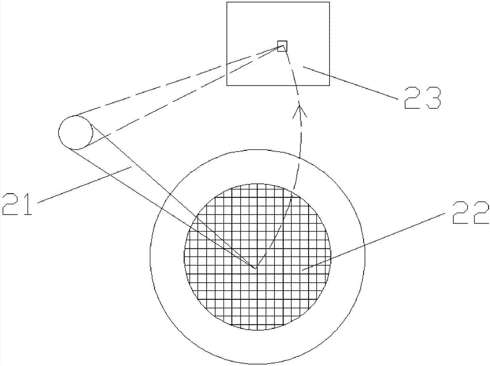
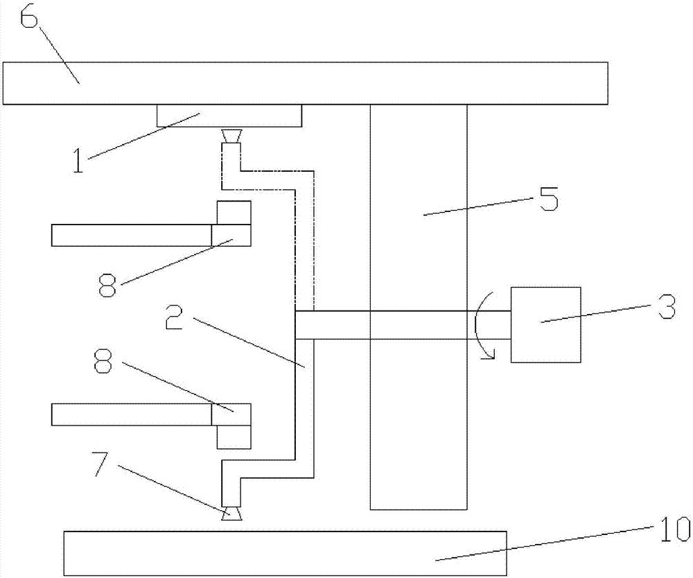
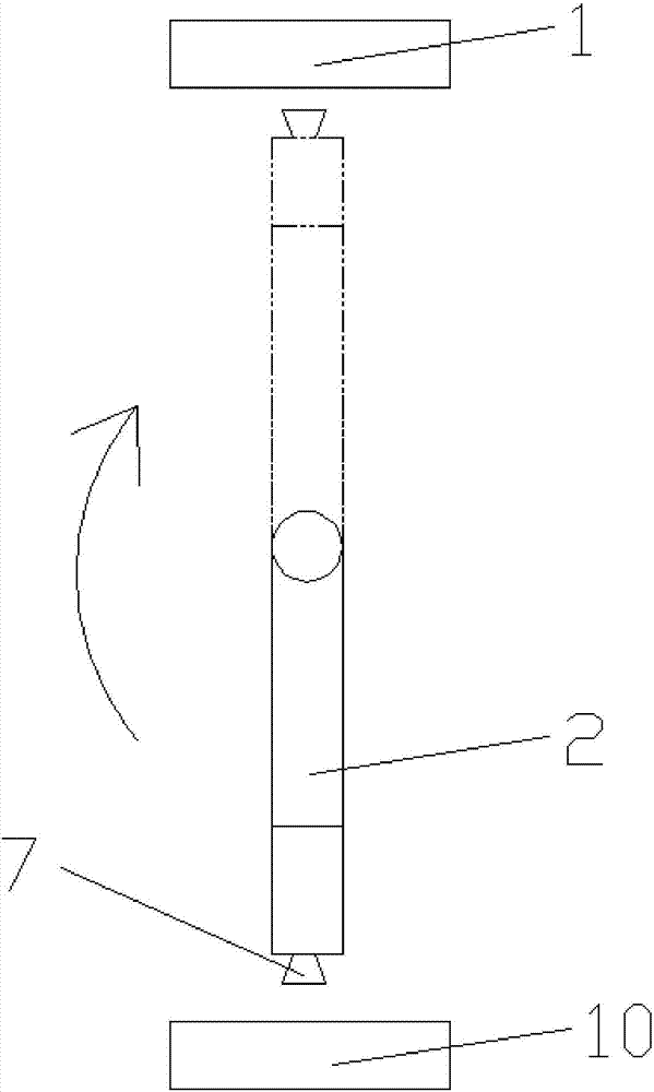
[0036] Below in conjunction with specific embodiments, the content of the present invention will be further described in detail: In order to achieve the purpose of the present invention, as shown in the figure, an embodiment of the present invention is: a vertical crystal removal and crystal fixation mechanism, including a wafer stage 1 , also includes: a first driving device 3 and a welding head assembly 5, the welding head assembly 5 is fixed on the support 6, the wafer table 1 is placed upside down above the welding head assembly 5, and the first driving device 3 is used to drive the welding head assembly 5 relative to The wafer table 1 rotates vertically and circularly. The welding head assembly 5 includes at least one welding head 7. The welding head 7 is used for crystal extraction and solid crystal. The rotation axis of the welding head assembly 5 is parallel to the wafer table 1. The welding assembly 5 has a section of The "Z"-shaped connecting arm 2, the welding head 7...


PUM


Abstract

The invention discloses a vertical grain taking and die bonding mechanism comprising a wafer table, a first drive unit, and a welding head assembly. The first drive unit is used for driving the welding head assembly to make vertical circumferential rotation relative to the wafer table. The welding head assembly includes at least one welding head for carrying out grain taking and die bonding; and the rotation axis of the welding head assembly is parallel to the wafer table. The mechanism has the following beneficial effects: the welding head makes a vertical circumferential motion along the wafer table above or below the wafer table; when grain taking and die bonding are carried out, the motion track of the welding head relative to the wafer table is an arc one; on the basis of the vertical circumferential rotation of the welding head, the horizontal motion distance of the welding head can be reduced; adaptability to substrates with different dimensions is high; the horizontal motion time is short during the grain taking and die bonding processes; the production efficiency can be improved substantially; and the production cost can be lowered.

Description

technical field [0001] The invention relates to the field of crystal-bonding machines, in particular to a vertical crystal-taking mechanism, a crystal-bonding mechanism and a vertical crystal-bonding machine using the same. Background technique [0002] Die bonding is an extremely important link in the packaging process of semiconductor devices such as ICs and LEDs. The process of solid crystal is: first, the dispensing mechanism (also called glue dispensing module) dispenses glue on the solid crystal station of the substrate, and then the solid crystal mechanism (also known as solid crystal head) removes the semiconductor die from the wafer Take it out, and then transfer it to the crystal-bonding station where the glue has been dispensed. Under the same die-bonding yield (quality) conditions, the die-bonding efficiency of the die-bonding machine is an important indicator for evaluating the performance of the die-bonding machine. [0003] The main welding head of the exist...

Claims


Application Information

Patent Timeline
Patent Type & Authority Applications(China)
IPC IPC(8): H01L21/67
CPCH01L21/67005H01L21/67121
Inventor 王敕关蕊
Owner SUZHOU ACCURACY ASSEMBLY AUTOMATION CO LTD
Why Eureka
Try Eureka