Shuttle valve having two drives

A driver and shuttle valve technology, applied in the field of shuttle valves, can solve the problems that the isolation valve is not suitable for adjusting the flow, cannot accurately perform and adjust the rotational motion, and cannot accurately perform and adjust the translational motion, etc. Simple design, precise adjustment of the effect of the task

Active Publication Date: 2008-01-23
VAT HLDG AG
View PDF10 Cites 7 Cited by
  • Summary
  • Abstract
  • Description
  • Claims
  • Application Information

AI Technical Summary

Problems solved by technology

Due to sealing and drive technology, partially manually operated isolating valves are not suitable for adjusting the flow rate, because neither the translat

Method used


Image

  • Shuttle valve having two drives
  • Shuttle valve having two drives
  • Shuttle valve having two drives

Examples


Embodiment Construction

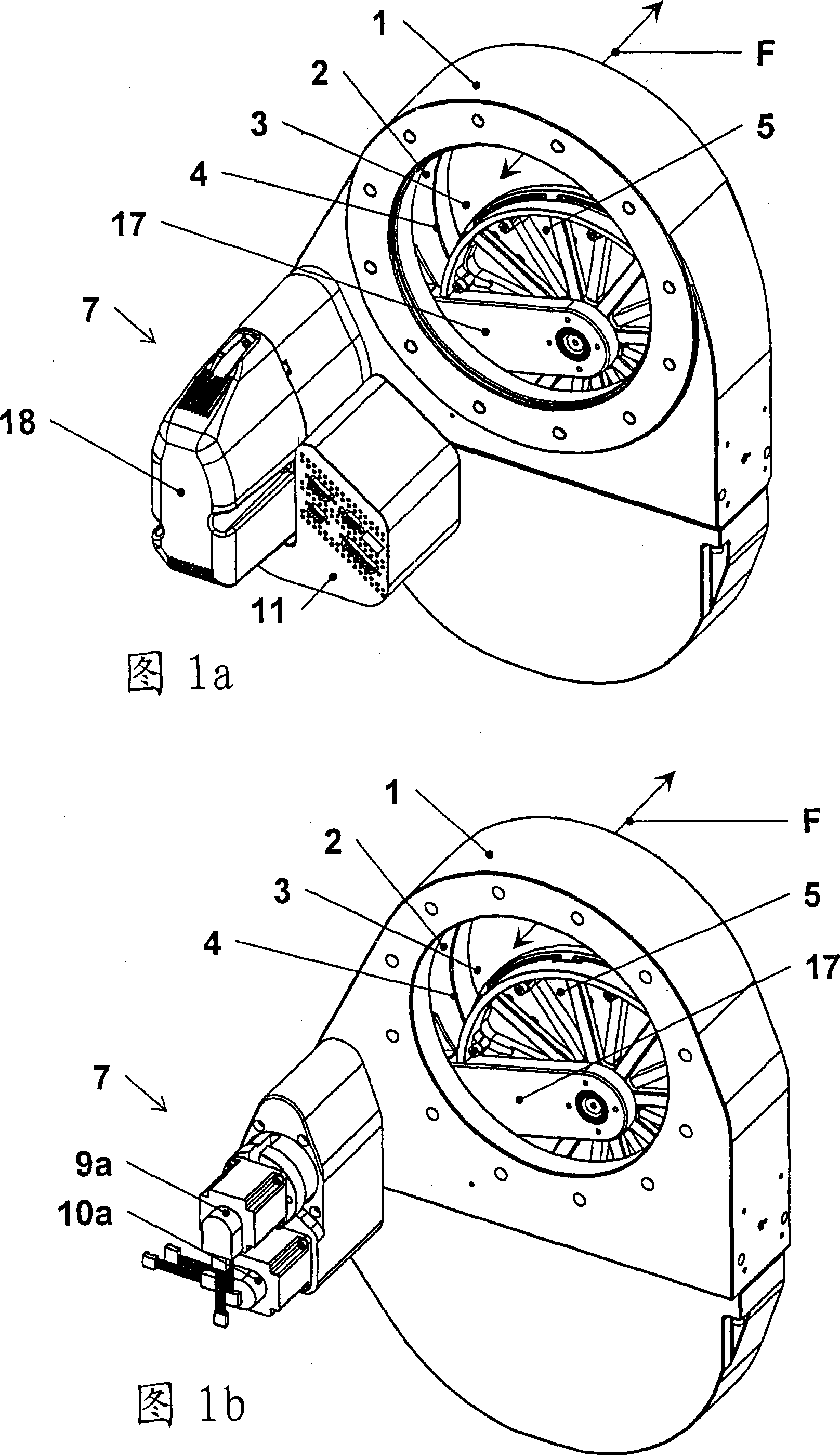
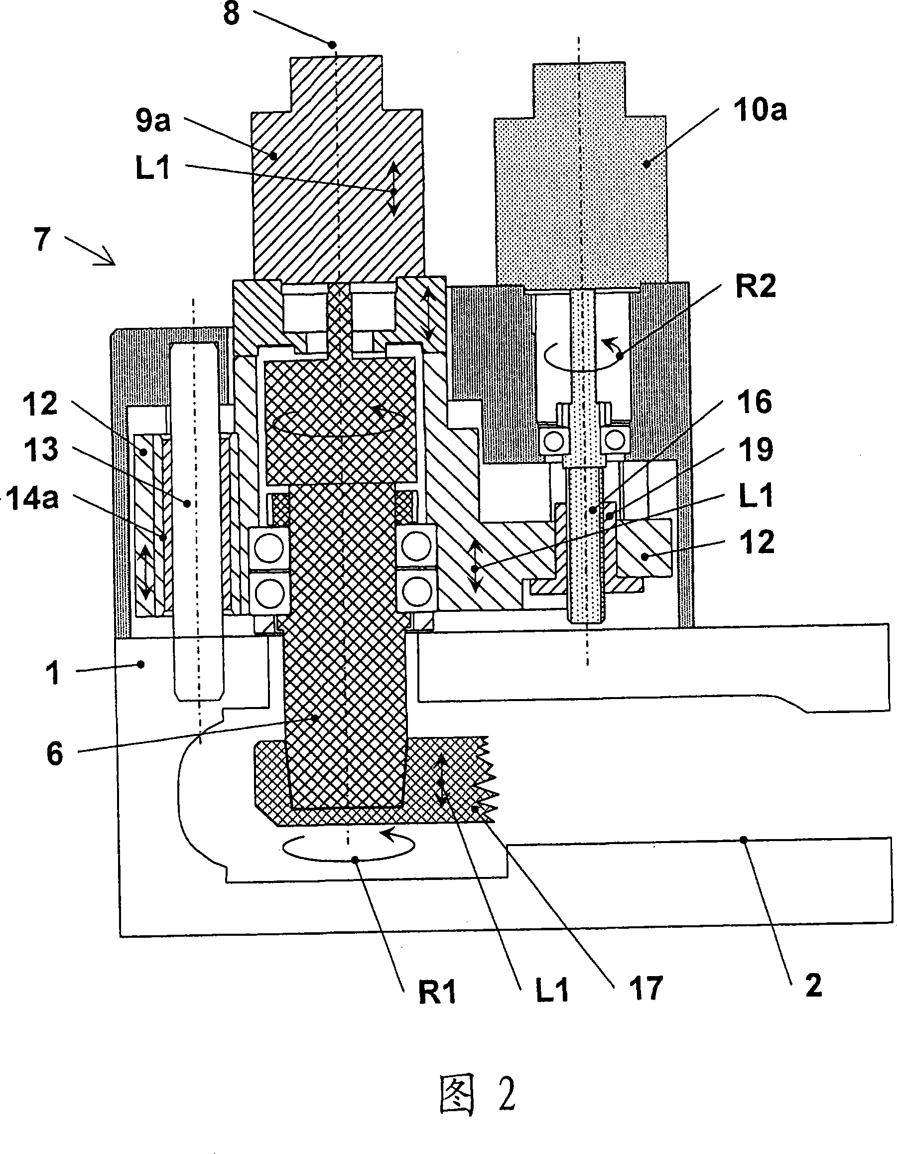
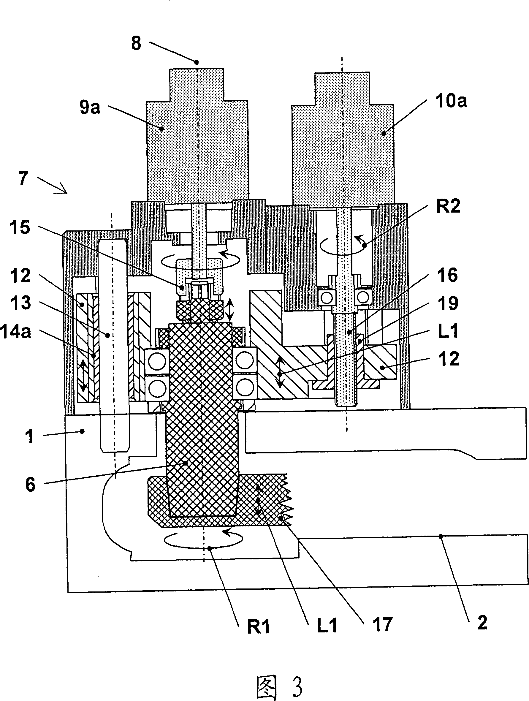
[0032] Figures 1a, 1b and 2 generally show an embodiment of the invention in different views, states and levels of detail, and these figures are therefore in some cases described together. Figures 2 to 6 each show an alternative embodiment of the drive unit. Since the figures in some cases use common reference numerals and the embodiments described in some cases have common features, reference numerals already explained above will partly be omitted.

[0033] Figures 1a and 1b show a shuttle valve comprising a valve housing 1 having a circular opening 3 in a wall 2 for a flow path F for a gas indicated by an arrow. The opening 3 is surrounded by a valve seat 4 formed by the edge portion of the wall 2 directed towards the interior of the valve housing 1 . Inside the valve housing 1 , a flat multi-part valve disc 5 is arranged pivotable on said opening 3 by means of an arm 17 . The shuttle valve has a drive unit 7 by means of which the valve disk 5 can be rotated on the opening...


PUM


Abstract

The invention relates to a shuttle valve for interrupting a flow path (F), comprising a valve housing ( 1 ) having a valve seat ( 4 ) surrounding an opening ( 3 ) for the flow path (F). A valve disc ( 5 ) is arranged on a rotatably mounted shaft ( 6 ). By means of a drive unit ( 7 ), the valve disc ( 5 ) can be swivelled along a defined displacement curve (K 1; K 2; K 3 ) from an opened position and leaving the flow path (F) unobstructed over the cross-section of the first opening ( 3 ) by a rotational movement about the pivot axis ( 8 ) of the shaft ( 6 ) and can be moved by a linear movement parallel to the pivot axis ( 8 ) in the direction of the valve seat ( 4 ) into a closed position so that the flow path (F) is sealed gas-tight by a sealing contact between the valve disc ( 5 ) and the valve seat ( 4 ). According to the invention, the drive unit ( 7 ) has a first drive ( 9 a) for carrying out the rotational movement about the pivot axis ( 8 ) and a second drive ( 10 a) for carrying out the linear movement parallel to the pivot axis ( 8 ). By means of a control unit ( 11 ), the first drive ( 9 a) and the second drive ( 10 a) can be actuated so that a variable displacement curve (K 1; K 2; K 3 ) can be produced.

Description

technical field [0001] The invention relates to a shuttle valve according to the preamble of claim 1, which shuts off substantially gas-tightly by rotating a valve disc over an opening and pressing the valve disc against a valve seat surrounding the opening. Cut off the flow path. Such a valve is described in US 6,089,537 (Olmsted). Background technique [0002] Various embodiments of valves of the type mentioned at the outset are known in the prior art and are used in particular in the field of IC and semiconductor manufacturing, which must be carried out in a protected environment which is as free as possible of contaminating particles. Shuttle valves are used, for example, to control or regulate the gas flow between the process chamber and the vacuum pump and, for example, as isolation valves or control valves. Isolation valves are mainly used to completely open and close channels, whereas control valves are formed for establishing a certain flow profile or regulating o...

Claims


Application Information

Patent Timeline
IPC IPC(8): F16K3/06F16K3/10F16K31/04F16K31/12F16K51/02
CPCF16K51/02F16K31/04F16K3/04
Inventor 弗洛里安·埃尔内
Owner VAT HLDG AG
Why Eureka
Try Eureka