Mould locking device structure of hollow plastic product forming machine

A technology for plastic products and mold clamping devices, which is applied in the field of mold clamping device structures, can solve problems such as increased cost of use, troublesome manufacturing and assembly, complex overall structure, etc., and achieves the effects of prolonging service life, concise overall structure, and convenient use

Active Publication Date: 2015-07-01
SUZHOU TONGDA MACHINERY
View PDF6 Cites 14 Cited by
  • Summary
  • Abstract
  • Description
  • Claims
  • Application Information

AI Technical Summary

Problems solved by technology

Yet this CN102848558A still has the following defects: one, because the clamping action cylinder column capture mechanism is made of a pair of action cylinders (the patent application is called the upper action cylinder and the lower action cylinder) and the action cylinder columns connected with the action cylinders of the pair of action cylinders respectively. The upper meshing clamp block and the lower meshing clamp block are formed, and the sides of the upper and lower meshing clamp blocks face each other to form semi-circular teeth. The cylinder columns on the column are engaged to put the mold halves on the left and right mold bases in the desired clamping state, so the overall structure is more complicated, which causes troubles in manufacturing and assembly; Abrasion will occur after repeated actions, so it is difficult to maintain a long-lasting matching effect, because once the semi-circular ring teeth and / or cylinder column meshing teeth are worn, the gap between the teeth will gradually increase, and the clamping effect will gradually weaken, eventually affecting the hollow The quality of plastic products, such as leaving obvious parting lines or flashes on hollow plastic products, unless the aforementioned upper and lower engaging clamps and clamping cylinders are replaced in time, but replacing these parts affects production efficiency on the one hand, On the other hand, it increases the cost of use

Method used


Image

  • Mould locking device structure of hollow plastic product forming machine
  • Mould locking device structure of hollow plastic product forming machine

Examples


Embodiment

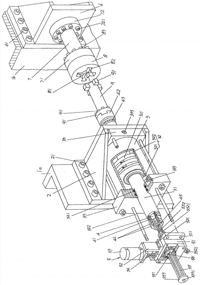
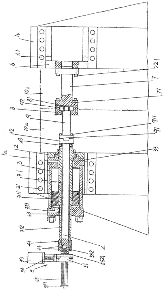
[0025] Please see figure 1 , the left mold base 1a and right mold base 1b belonging to the structural system of the hollow plastic product molding machine are given. According to professional knowledge, the left half mold 10a is installed on the left mold base 1a ( figure 2 shown), and on the right mold base 1b and at the position corresponding to the left half mold 10a, the right half mold 10b is installed ( figure 2 Show). Furthermore, according to professional common sense, between the left and right formworks 1a and 1b, it is usually necessary to set a plurality of the same structure, such as two, four or six mold clamping device structures belonging to the structural system of the present invention. The specific reason can be found in Paragraph 0025 of the description of China Invention Patent Authorization Announcement No. CN101890805B and Publication No. CN102848558A.

[0026] The following is for one of the multiple clamping device structures arranged between the lef...


PUM


Abstract

The invention discloses a mould locking device structure of a hollow plastic product forming machine, which belongs to the technical field of plastic product forming machines. The hollow plastic product forming machine comprises left and right mould bases. The mould locking device structure comprises a pair of deflection rod displacement action cylinder bases, a deflection rod displacement action cylinder, a deflection rod, a deflection rod rotating actuating mechanism, a pull rod base, a pull rod, a pin lock and a pin lock key, wherein the deflection rod displacement action cylinder bases are fixed on one side, which faces to the right mould base, of the left mould base; the deflection rod displacement action cylinder is fixed on the deflection rod displacement action cylinder bases and is provided with a piston; the deflection rod is arranged in a deflection rod hole; the deflection rod rotating actuating mechanism is arranged the left one in the pair of deflection rod displacement action cylinder bases of the deflection rod displacement action cylinder and is connected with the left end of the deflection rod; the pull rod base is fixed on one side, which faces to the left mould base, of the right mould base, and the pull rod base and the deflection rod displacement action cylinder bases correspond to each other; the pull rod is fixed on the pull rod base; the pin lock is fixed on the pull rod; the left end of the pin lock key is connected with a tabling joint of the deflection rod, and the right end of the pin lock key is matched with the pin lock. The mould locking device structure provided by the invention has the advantages that the module combining effect of left and right half modules is guaranteed, the service life is prolonged, and the integral structure is simple.

Description

technical field [0001] The invention belongs to the technical field of plastic product molding machines, and in particular relates to a mold clamping device structure of a hollow plastic product molding machine. Background technique [0002] As is well known in the industry, a hollow plastic product molding machine includes a machine base, a mold base moving device arranged on the machine base, and is connected to the mold base moving device and closed or mutually repelled under the work of the mold base moving device. The left and right mold bases and the clamping device installed between the left and right mold bases, one of the pair of half molds for blowing plastic products is installed on the left mold base, while the other half mold Installed on the right mold base, the left and right molds correspond to each other. When closing the mould, firstly the mold base moving device works to make the left and right mold bases close together, the left and right mold bases toge...

Claims


Application Information

Patent Timeline
Patent Type & Authority Patents(China)
IPC IPC(8): B29C49/56
Inventor 邱建成
Owner SUZHOU TONGDA MACHINERY
Why Eureka
Try Eureka