Wire and cable transport and pay-off vehicle

A technology for wire and cable and pay-off car, which is applied to cable laying equipment and other directions, can solve the problems of increasing the use cost of cranes, high cost, inconvenient operation, etc., and achieve the effect of improving work efficiency of pay-off, wide application range and simple structure.

Active Publication Date: 2016-05-04
STATE GRID CORP OF CHINA +2
View PDF10 Cites 0 Cited by
  • Summary
  • Abstract
  • Description
  • Claims
  • Application Information

AI Technical Summary

Problems solved by technology

[0002] In the process of erecting transmission lines, conductor transportation and pay-off are the two main links in the construction process, especially the loading and unloading of the spools. The spools weighing hundreds of kilograms or even several tons are very heavy, and it is necessary to hire a crane to load them from the warehouse to the transport vehicle. After being transported to the construction site, the crane is used to unload the truck to the designated place, and then the spool is loaded onto the original pay-off rack by manpower on the shoulders, and then the pay-off construction can be started. First, the cost of using the crane is increased. If The construction site is narrow, it is difficult for the crane to enter the construction site, and the cost of using the crane is higher; second, it is difficult to place the wires in a suitable position for setting out the wire, and it is inconvenient; third, there are a large number of construction personnel; Hidden danger
The entire construction process is inconvenient to operate, inaccurate in positioning, time-consuming, laborious, costly, and inefficient

Method used


Image

  • Wire and cable transport and pay-off vehicle
  • Wire and cable transport and pay-off vehicle
  • Wire and cable transport and pay-off vehicle

Examples


Embodiment Construction

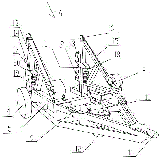
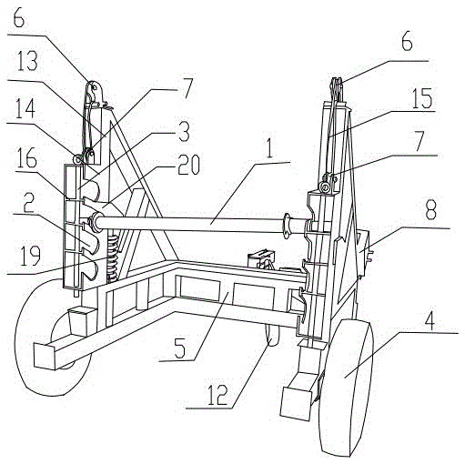
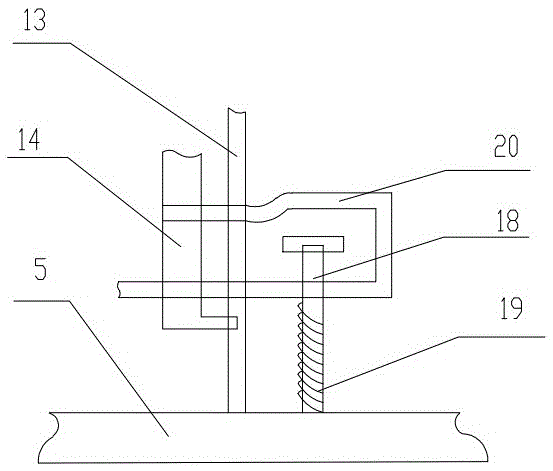
[0021] see Figure 1 ~ Figure 3 , the invention discloses a wire and cable transport and pay-off vehicle, which includes wheels 4, a vehicle frame 5 and tractor connecting buckles 11 arranged at the front of the vehicle frame 5, and the columns 13 on both sides of the vehicle frame 5 are respectively provided with symmetrical The threading shaft lifting mechanism, the threading shaft lifting mechanism includes a lifting frame 14 with more than one open slot 2, the lifting frame 14 and the column 13 are slidingly matched, and the lifting frame 14 is connected to the fixed pulley 6 on the upper end of the steel wire rope 15 and the column 13. The rope rollers on both sides of the vehicle frame 5 are connected to the lifting self-locking drive mechanism; the threading shaft 1 is placed in the corresponding open slots 2 on both sides, and a threading shaft anti-slip mechanism is provided.

[0022] The lifting self-locking driving mechanism is a hand-operated worm gear reducer 8 . ...


PUM


Abstract

The invention discloses an electric wire and cable transportation and paying-off vehicle, and relates to the technical field of electric power line erection work tools. The electric wire and cable transportation and paying-off vehicle comprises wheels, a vehicle frame and a towing tractor connecting buckle arranged on the front portion of the vehicle frame, wherein symmetrical line penetrating shaft lifting mechanisms are arranged on stand columns on the two sides of the vehicle frame respectively, each line penetrating shaft lifting mechanism comprises a lifting frame which is provided with more than one opening type clamping groove, the lifting frames are in slide fit with the stand columns, the lifting frames are connected with rope rollers on the two sides of the vehicle frame and lifting self-locking driving mechanisms on the two sides of the vehicle frame through steel wire ropes and fixed pulleys at the upper ends of the stand columns, and line penetrating shafts are arranged in the corresponding opening type clamping grooves on the two sides respectively and provided with line penetrating shaft anti-slipping mechanisms respectively. The device is simple in structure, allows spools to be conveniently hoisted, transported and paid off, saves time, labor and cost, is accurate, safe and high in efficiency, and meets the actual requirements for spool transportation and paying off.

Description

technical field [0001] The invention relates to the technical field of power line erection work tools. Background technique [0002] In the process of erecting transmission lines, conductor transportation and pay-off are the two main links in the construction process, especially the loading and unloading of the spools. The spools weighing hundreds of kilograms or even several tons are very heavy, and it is necessary to hire a crane to load them from the warehouse to the transport vehicle. After being transported to the construction site, the crane is used to unload the truck to the designated place, and then the spool is loaded onto the original pay-off rack by manpower on the shoulders, and then the pay-off construction can be started. First, the cost of using the crane is increased. If The construction site is narrow, it is difficult for the crane to enter the construction site, and the cost of using the crane is higher; second, it is difficult to place the wires in a suit...

Claims


Application Information

Patent Timeline
Patent Type & Authority Patents(China)
IPC IPC(8): H02G1/06
Inventor 龙建勇卫郭喜翟文涛
Owner STATE GRID CORP OF CHINA
Why Eureka
Try Eureka