Motor speed control device and speed control method

A speed control, motor technology, applied in the direction of AC motor control, control system, electrical components, etc., can solve problems such as implementation difficulties

Active Publication Date: 2016-08-10
安川电机(中国)有限公司
View PDF4 Cites 0 Cited by
  • Summary
  • Abstract
  • Description
  • Claims
  • Application Information

AI Technical Summary

Problems solved by technology

However, it is very difficult to carry out such a combined test in the face of common frequency converters on the market. Therefore, it is necessary to seek a method that can easily avoid the stall state of the motor without performing a combined test, and can also be used in a shorter period of time. The speed control device and the speed control method for reaching the target speed within a certain time

Method used


Image

  • Motor speed control device and speed control method
  • Motor speed control device and speed control method
  • Motor speed control device and speed control method

Examples


Embodiment Construction

[0038] In the field of spindle drive, the dedicated motor for the spindle is generally driven by an inverter, and the workpiece is rotated by the dedicated motor for the spindle, and the workpiece is processed by feeding the cutting tool. However, the price of the special motor for the spindle is relatively high, so it is considered to replace the special motor for the spindle with an ordinary motor.

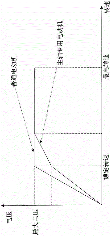
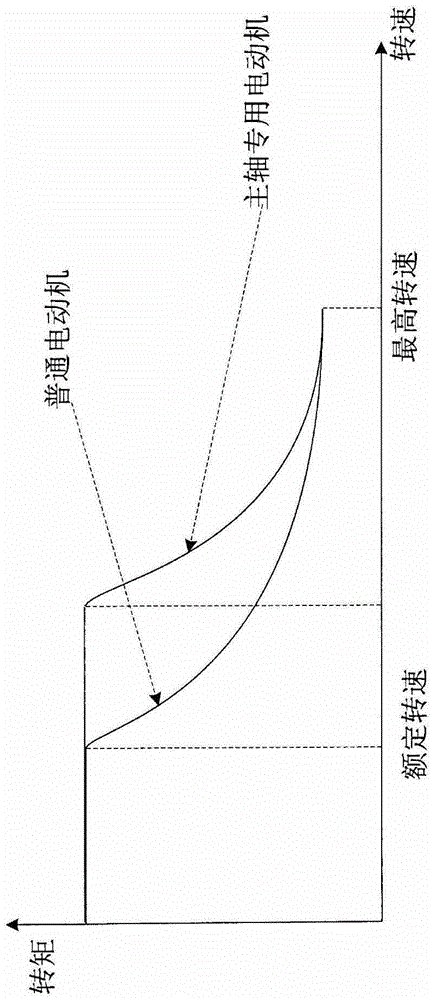
[0039] Fig. 1(A) shows the relationship curve between the speed of the spindle special motor and the general motor and the output voltage of the frequency converter, and Fig. 1(B) shows the speed-torque curve of the spindle special motor and the general motor. As shown in Figure 1(A), when an ordinary motor reaches the rated speed (for example, 1500rpm), the output voltage of the frequency converter reaches the maximum value, which is called the voltage saturation state. Since the output voltage reaches the maximum value, the power of the motor is also limited, and the power of ...


PUM


Abstract

The invention relates to a speed control device and a speed control method of a motor. For the combination of a common frequency converter and a motor in the market, the stall state of the motor can be easily avoided, and the motor can reach a target speed in a short time. Wherein, the speed control device includes: a soft start unit, a speed control unit, an interruption unit, and a motor speed detection unit.

Description

technical field [0001] Embodiments of the present invention relate to a rotational speed control device and a rotational speed control method of an electric motor. Background technique [0002] In the field of main shaft drive of machine tools, AC frequency conversion speed regulation in which an asynchronous motor (hereinafter referred to as a motor) is driven by a frequency converter has become the mainstream. [0003] The motor takes the rated speed as the demarcation point, and can be used in the constant torque area where the speed is less than the rated speed and the constant output area where the speed is greater than the rated speed. In the constant output area, the maximum output torque of the motor decreases with the increase of the motor speed. Therefore, when the motor is used in a constant output area, its maximum output torque may be lower than the sum of the required load torque and acceleration torque during the continuous acceleration of the motor. When th...

Claims


Application Information

Patent Timeline
Patent Type & Authority Patents(China)
IPC IPC(8): H02P27/04
Inventor 陈鸣野中和浩福井耕平寺园裕一陈喆
Owner 安川电机(中国)有限公司
Why Eureka
Try Eureka