buffer roller

A technology of buffer rollers and steering wheels, which is applied in sawing machine devices, metal sawing equipment, metal processing equipment, etc., can solve the problems of complex structure and disadvantage.

Inactive Publication Date: 2016-06-22
费尔有限公司
View PDF8 Cites 0 Cited by
  • Summary
  • Abstract
  • Description
  • Claims
  • Application Information

AI Technical Summary

Problems solved by technology

Disadvantages here are, in particular, the complex design and the fact that due to the conveyed fluid it is not possible to use in all applications

Method used


Image

  • buffer roller
  • buffer roller
  • buffer roller

Examples


Embodiment Construction

[0024] At the outset, it should be emphasized that in the differently described embodiments, the same parts are assigned the same reference symbols or the same component symbols, wherein the disclosure content contained in the entire description can be transferred without meaning to Figure marks or the same component marks on the same part. Positional indications selected in the description, such as top, bottom, side, etc., also refer to the directly described and depicted figures and can be transferred to the new position in the event of a position change. Furthermore, individual features or combinations of features in the different exemplary embodiments shown and described can themselves be independent, inventive or solutions according to the invention.

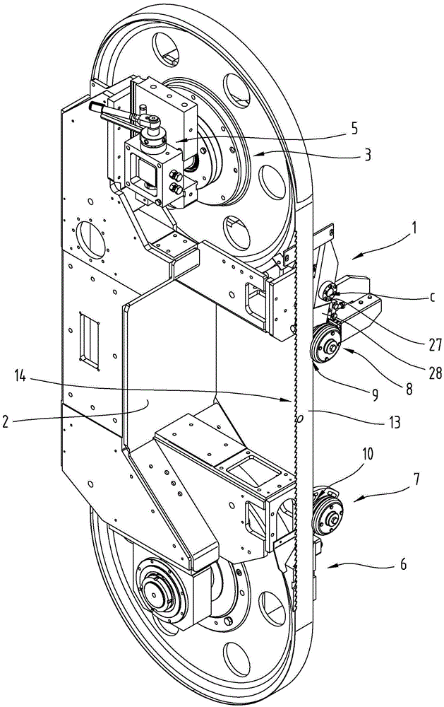
[0025] according to figure 1 The band saw device 1 according to the invention can have a base frame 2 and two deflection wheels 3 , 4 arranged at a distance from one another. In addition, a drive means 5 can be provided, ...


PUM


Abstract

The invention relates to a band saw device (1) comprising a base frame (2), at least two deflection wheels (3, 4) which are arranged at a distance from each other, drive means (5) which are in a driving engagement with at least one of the deflection wheels (3, 4) and a band saw blade (6) continuously circulating the deflection wheels (3, 4). The band saw blade (6) is frictionally engaged with at least one damping roller (7) in the region of one side of the saw arranged between both deflection rollers.

Description

technical field [0001] The invention relates to a band saw device comprising a base frame, at least two deflection wheels arranged at a distance from each other, a drive device connected in transmission with at least one of the deflection wheels and a continuous A ground-circling band saw blade, wherein the band saw blade is frictionally connected to at least one buffer roller in the region of the saw side between the two deflection rollers. Background technique [0002] During the sawing process, especially at the beginning of the cutting process into the workpiece to be sawed, there are often jerky and oscillating positions of the band saw blade. This leads to shape deviations and high values ​​of the surface roughness in the cutting area. For this reason, guides are usually provided in order to run the saw band in a defined manner. However, a certain degree of freedom of movement of the band saw blade can be achieved by means of the play in the guide. However, these kn...

Claims


Application Information

Patent Timeline
Patent Type & Authority Patents(China)
IPC IPC(8): B23D55/08
CPCB23D55/082
Inventor A·博伊德克尔F·施特拉塞尔
Owner 费尔有限公司
Why Eureka
Try Eureka