Elastic joint body

An elastic connector, elastic technology, applied in elastic couplings, mechanical equipment, couplings, etc., can solve problems such as increasing the maximum torque

Active Publication Date: 2014-01-29
SGF SUDDEUTE GELENKSCHEIBENFAB
View PDF7 Cites 7 Cited by
  • Summary
  • Abstract
  • Description
  • Claims
  • Application Information

AI Technical Summary

Problems solved by technology

However, they do not involve a considerable increase in the maximum torque that can be transmitted in continuous operation

Method used


Image

  • Elastic joint body
  • Elastic joint body
  • Elastic joint body

Examples


Embodiment Construction

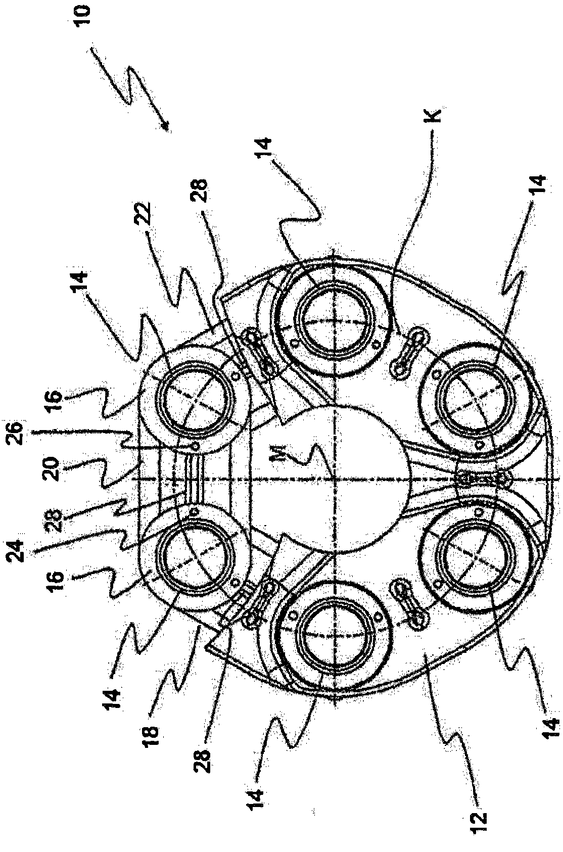
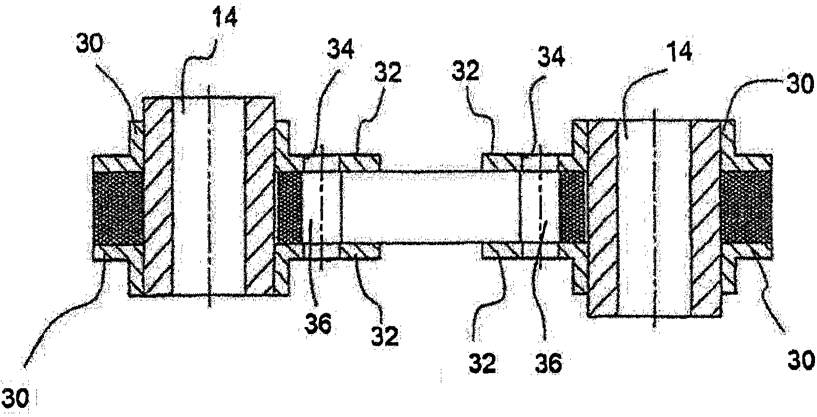
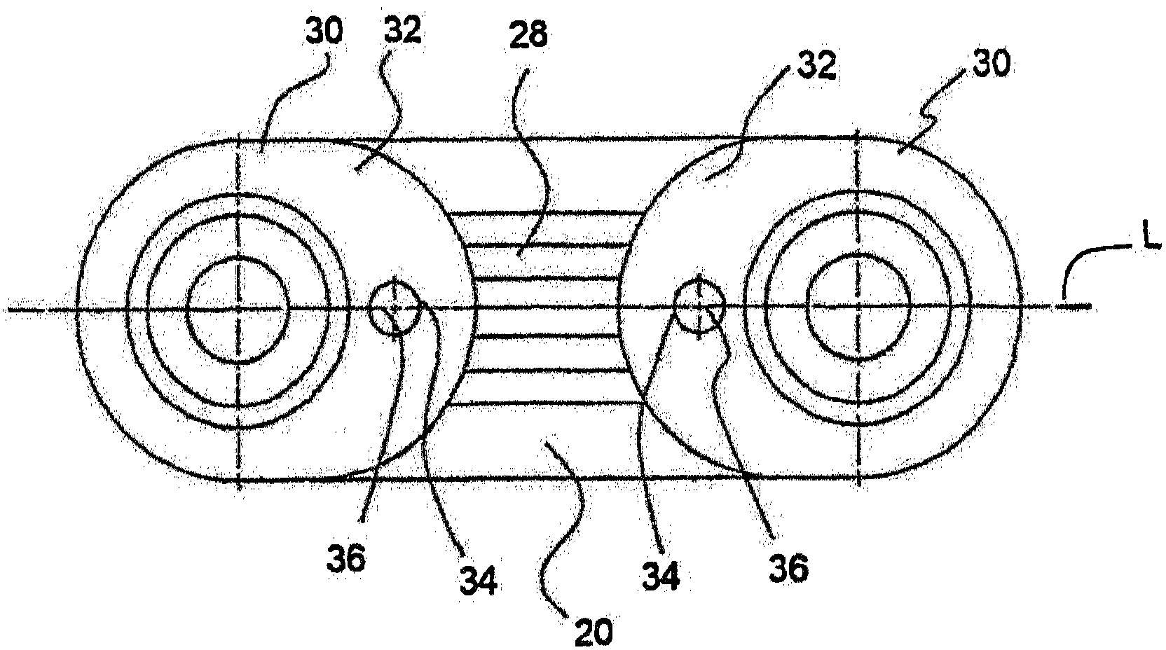
[0032] figure 1A partially cut-away plan view is shown of an elastic connecting body 10 according to the invention having six bushings 14 surrounded by a rubber elastic casing 12 . The bushings 14 are arranged in predetermined corners of the connecting body 10 in the circumferential direction with respect to the center axis M in such a way that their center points lie on the circular path K. As shown in FIG. in accordance with figure 1 In the portion of the connecting body of , which is shown cut away in the figure, the collar element 16 on the bushing 14 can be seen, which is arranged to axially support the ring bundles 18 , 20 and 22 . figure 1 It is also shown that on the collar element 16 two corresponding pegs 24 (or stakes) are received in receiving openings 26 in areas facing each other. A respective auxiliary loop 28 extending within the loops 18 , 20 , 22 is guided around each of these staples 24 .

[0033] figure 1 Also shown are a plurality of loop bundles 18 , ...


PUM


Abstract

The invention relates to an elastic joint body (10) for a shaft arrangement for connecting two shaft portions in an articulated manner, comprising - a plurality of bushings (14) - at least one primary loop bundle (18, 20, 22), each of which loops a bushing pair consisting of two adjacent bushings (14), said pair being loadable in tension in the event of a torque transfer via the shaft portions, - a support device (26) arranged on at least one bushing for axially guiding the primary loop bundle (18, 20, 22), and - an elastomeric casing (12) into which the loop bundle (18, 20, 22), the support devices (26), and the bushings (14) are at least partly embedded. The adjacent bushings (14) of at least some of the bushing pairs are connected to each other in a force-transmitting manner via at least one additional loop bundle (28), said at least one additional bundle (28) being arranged in the elastomeric casing (12) in a region in which none of the primary loop bundles (18, 20, 22) extend.

Description

technical field [0001] The invention relates to an elastic connecting body for a shaft structure connecting two shaft parts in an articulated manner, having a plurality of bushings, at least one main ring bundle, a ring arranged on at least one bushing for axially guiding the main ring bundle The support means, and the rubber elastic housing in which the ring bundles, support means and bushings are at least partially embedded, wherein each main ring bundle is looped around a pair of bushings, the pair of bushings comprising two adjacent bushings and Tension is applied to the shaft when torque is transmitted. Background technique [0002] Elastic connectors of this type are already known from the prior art. This also relates to connecting discs, which are used, for example, in the drive train of a motor vehicle—to a lesser extent—in the steering column of a motor vehicle to connect two axles in a torque-transmitting manner. The advantages of this type of connecting discs ar...

Claims


Application Information

Patent Timeline
Patent Type & Authority Applications(China)
IPC IPC(8): F16D3/62F16D3/78
CPCF16D3/78F16D3/62
Inventor 贝尔恩德·沙珀尔约瑟夫·斯杜本劳赫尤尔根·莱茵菲尔德马克·布兰德尔沃尔夫冈·尼恩戴尔
Owner SGF SUDDEUTE GELENKSCHEIBENFAB
Why Eureka
Try Eureka