Hydraulic transmission apparatus

a transmission apparatus and hydraulic technology, applied in the direction of rotary clutches, fluid couplings, gearings, etc., can solve the problems of reducing the torque of the fluid coupling, and the inability to transmit the torque to the transmission side,

Inactive Publication Date: 2012-02-09
AISIN AW CO LTD
View PDF4 Cites 8 Cited by
  • Summary
  • Abstract
  • Description
  • Claims
  • Application Information

AI Technical Summary

Benefits of technology

[0013]According to a sixth aspect of the present invention, the frictional force generating mechanism may include a member that engages with one of the turbine runner and the input element of the damper mechanism with a clearance in the rotational direction, and may apply the frictional force to the input element when a twist angle of the dynamic damper that is formed by the turbine runner and the second elastic body becomes equal to or larger than the clearance. Thus, by determining the clearance according to the rotational speed range of the input member in which the resonance occurs in association with the use of the dynamic damper, the frictional force according to the vibration that is transmitted from the input element of the damper mechanism to the turbine runner can be more properly applied to the input element.
[0014]According to a seventh aspect of the present invention, the frictional force generating mechanism may be a multi-plate clutch mechanism that includes a first clutch plate that engages with one of the turbine runner and the input element of the damper mechanism with the clearance in the rotational direction, and a second clutch plate that engages with the other of the turbine runner and the input element of the damper mechanism. Thus, the frictional force according to the vibration that is transmitted from the input element of the damper mechanism to the turbine runner can be more properly applied to the input element when the rotational speed of the input member is included in the rotational speed range in which the resonance occurs in association with the use of the dynamic damper.

Problems solved by technology

However, in the above conventional hydraulic transmission apparatus, torque from the fluid coupling (the turbine) is transmitted to the transmission side via a damper mechanism, even when the lockup is being released.
Thus, the torque from the fluid coupling is damped by the damper mechanism, and required torque may not be able to be transmitted to the transmission side.

Method used


Image

  • Hydraulic transmission apparatus
  • Hydraulic transmission apparatus
  • Hydraulic transmission apparatus

Examples


Embodiment Construction

[0022]An embodiment of the present invention will be described below.

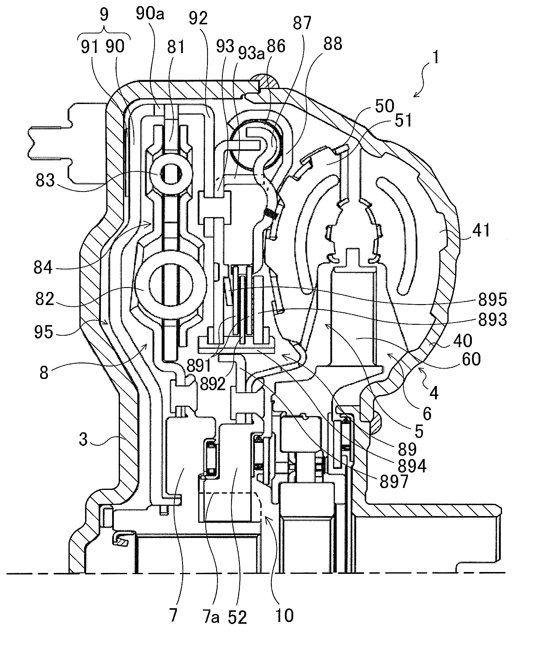
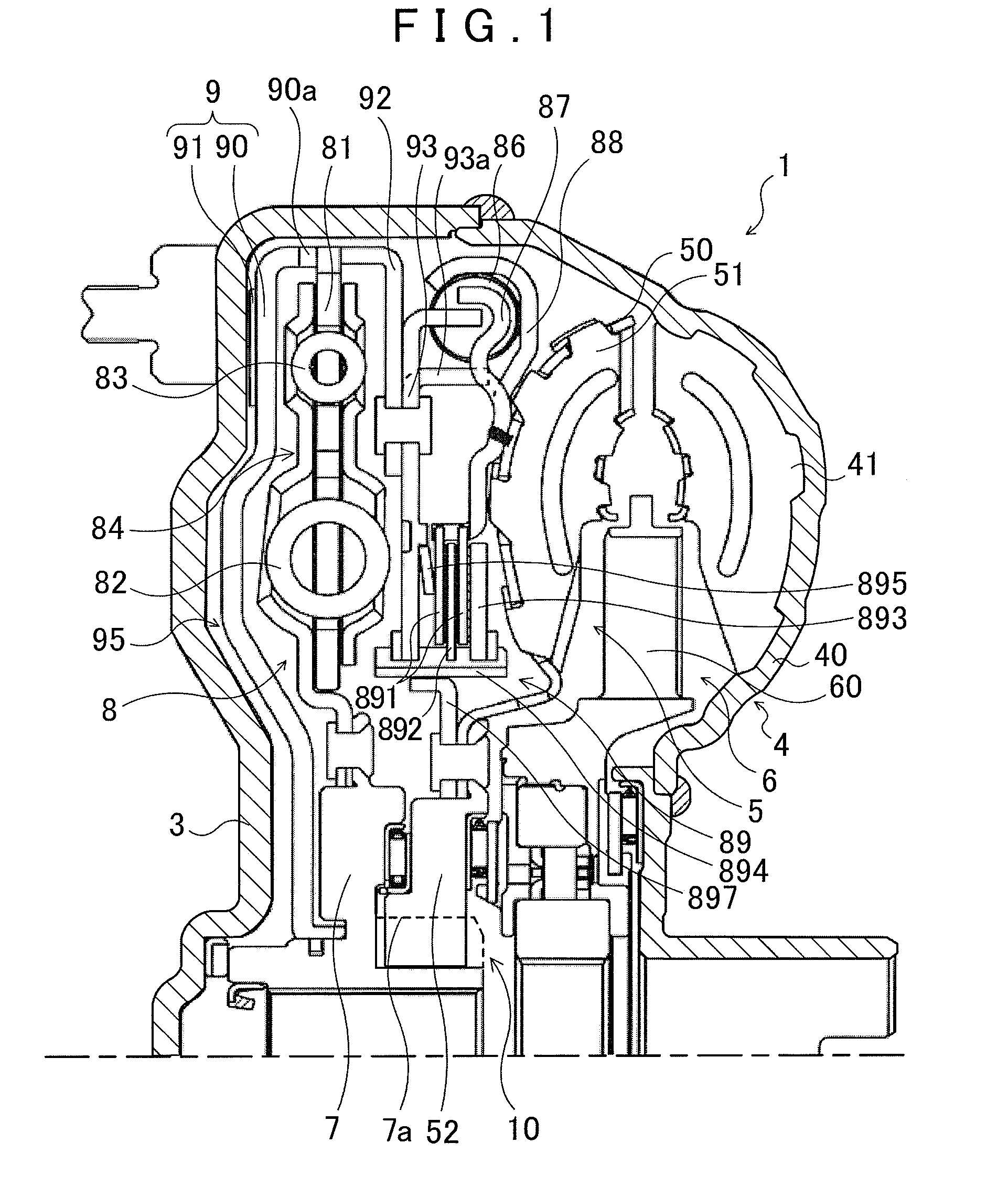
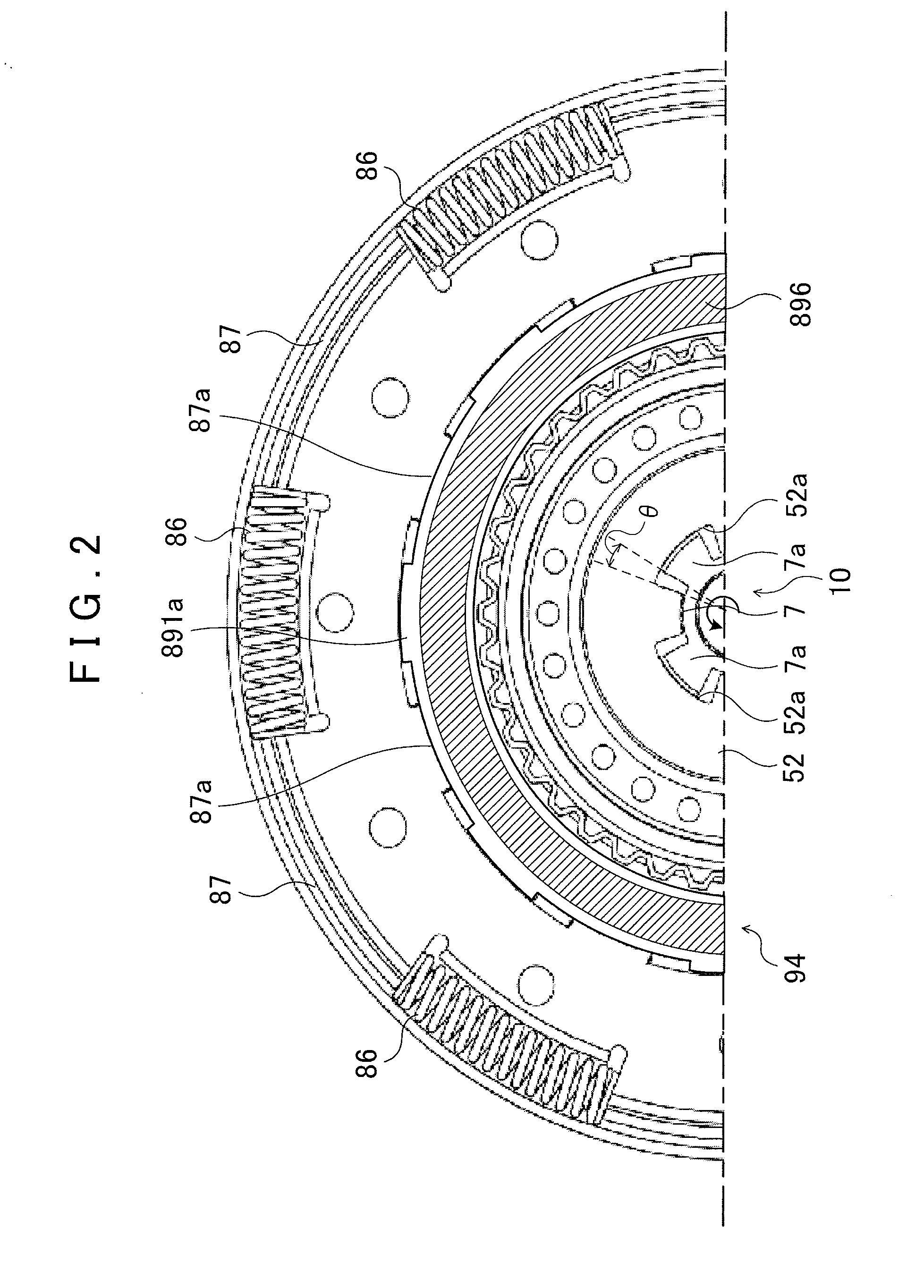
[0023]FIG. 1 is a partial cross-sectional view showing a hydraulic transmission apparatus 1 according to an embodiment of the present invention, and FIG. 2 is an enlarged view showing a main part of the hydraulic transmission apparatus 1. The hydraulic transmission apparatus 1 shown in these drawings is a torque converter that is mounted as a starting apparatus on a vehicle including an engine as a motor. The hydraulic transmission apparatus 1 includes: a front cover (an input member) 3 that is coupled to a crankshaft of the engine, not shown; a pump impeller (an input-side hydraulic transmission element) 4 fixed to the front cover 3; a turbine runner (an output-side hydraulic transmission element) 5 capable of rotating coaxially with the pump impeller 4; a stator 6 that straightens a flow of hydraulic oil (working fluid) from the turbine runner 5 to the pump impeller 4; a damper hub (an output member) 7 that is fi...


PUM


Abstract

A hydraulic transmission apparatus including a pump impeller connected to an input member that is coupled to a motor; a turbine runner for rotating with the pump impeller; a damper mechanism having an input element coupled to the turbine runner, an elastic body engaging with the input element, and an output element engaging with the elastic body and coupled to an transmission device input shaft; a lockup clutch for performing lockup in which the input member is engaged with the input element of the damper mechanism, and for releasing lockup; and an engagement mechanism engaging the turbine runner with the output element of the damper mechanism so that the turbine runner and the output element of the damper mechanism rotate integrally, when the lockup is released by the lockup clutch, and that does not engage the turbine runner with the output element of the damper mechanism so that the turbine runner and the output element of the damper mechanism do not rotate integrally, when the lockup is performed by the lockup clutch.

Description

INCORPORATION BY REFERENCE[0001]The disclosure of Japanese Patent Application No. 2010-178752 filed on Aug. 9, 2010 including the specification, drawings and abstract is incorporated herein by reference in its entirety.BACKGROUND OF THE INVENTION[0002]The present invention relates to hydraulic transmission apparatuses including a damper mechanism having an input element that is coupled to a turbine runner capable of rotating together with a pump impeller connected to an input member, and a lockup clutch capable of performing lockup in which the input member is engaged with the input element of the damper mechanism, and also capable of releasing the lockup.DESCRIPTION OF THE RELATED ART[0003]Hydraulic transmission apparatuses that have been conventionally proposed as this type of hydraulic transmission apparatus include: a lockup clutch coupled to a front cover that is coupled to a crankshaft of an engine; a fluid coupling that is formed by a pump impeller integral with the front cov...

Claims


Application Information

Patent Timeline
Patent Type & Authority Applications(United States)
IPC IPC(8): F16H45/02
CPCF16H45/02F16H2045/0205F16H2045/0294F16H2045/0231F16H2045/0284F16H2045/0226
Inventor TAKIKAWA, YOSHIHIROMARUYAMA, KAZUTOITOU, KAZUHIRO
Owner AISIN AW CO LTD
Why Eureka
Try Eureka