Receiving part for receiving a rod for coupling the rod to a bone anchoring element and a bone anchoring device

a technology for receiving parts and rods, which is applied in the field of receiving parts for coupling rods to bone anchoring elements and bone anchoring devices, can solve problems such as not contributing to effective clamping of the head, and achieve the effects of reducing the cost of polyaxial screws, improving the safety of fixing, and safe handling

Active Publication Date: 2012-07-12
BIEDERMANN TECH GMBH & CO KG
View PDF44 Cites 70 Cited by
  • Summary
  • Abstract
  • Description
  • Claims
  • Application Information

AI Technical Summary

Benefits of technology

[0007]It is an object of the invention to provide an improved receiving part for receiving a rod for coupling the rod to a bone anchoring element, and a bone anchoring device with such a receiving part, which allows for safe handling during surgery and safe fixation of the bone anchoring element and the rod.
[0008]A receiving part according to embodiments of the invention is improved with respect to clamping and locking of a head of a bone anchoring element. Exerting pressure by the locking ring at positions where a head receiving portion has slits may not contribute to an effective clamping of the head. Therefore, the bone anchoring device according to embodiments of the present invention is designed such that the pressure force exerted by the locking ring onto the head receiving portion is concentrated at distinct pressure areas separated from each other in a circumferential direction. Hence, the clamping force can be precisely applied, which improves the safety of the fixation.
[0009]Furthermore, the receiving part according to embodiments of the invention can have a pre-locking function, where the locking ring is latched with respect to the receiving part body in a position in which the head is inserted but is not yet locked, so that the head is prevented from removal from the receiving part.
[0010]With the bone anchoring device according to embodiments of the invention, a modular system can be provided that allows for combining various anchoring elements with any suitable receiving part on demand, depending on the specific clinical requirements. This reduces the costs associated with polyaxial screws, reduces inventory, and gives a surgeon a substantial or wider choice of implants.

Problems solved by technology

Exerting pressure by the locking ring at positions where a head receiving portion has slits may not contribute to an effective clamping of the head.

Method used


Image

  • Receiving part for receiving a rod for coupling the rod to a bone anchoring element and a bone anchoring device
  • Receiving part for receiving a rod for coupling the rod to a bone anchoring element and a bone anchoring device
  • Receiving part for receiving a rod for coupling the rod to a bone anchoring element and a bone anchoring device

Examples


first embodiment

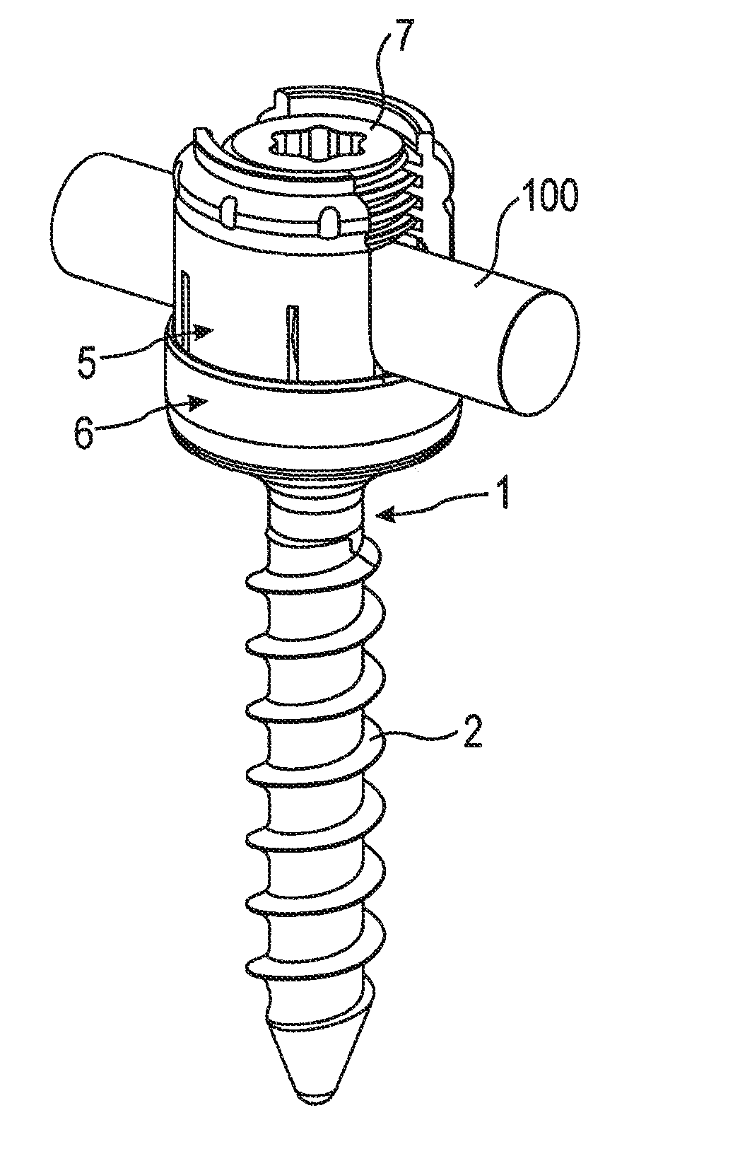
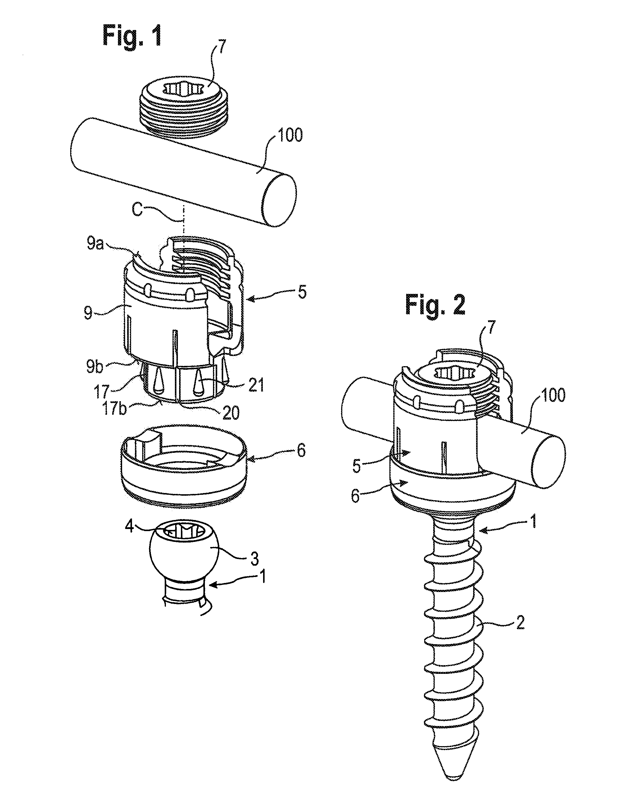
[0027]a bone anchoring device is shown in FIGS. 1 to 5c. The bone anchoring device includes a bone anchoring element 1 in the form of a bone screw having a threaded shaft 2 and a head 3 with a spherically-shaped outer surface portion. The head 3 has a recess 4 for engagement with a driver or tool. The bone anchoring device further includes a. receiving part body 5 for receiving a rod 100 to connect the rod 100 to the bone anchoring element 1. For locking the head 3 in the receiving part body 5, a locking ring 6 is provided that engages the receiving part body 5. Furthermore, a fixation device in the form of; for example, an inner screw 7 is provided for fixing the rod 100 in the receiving part body 5.

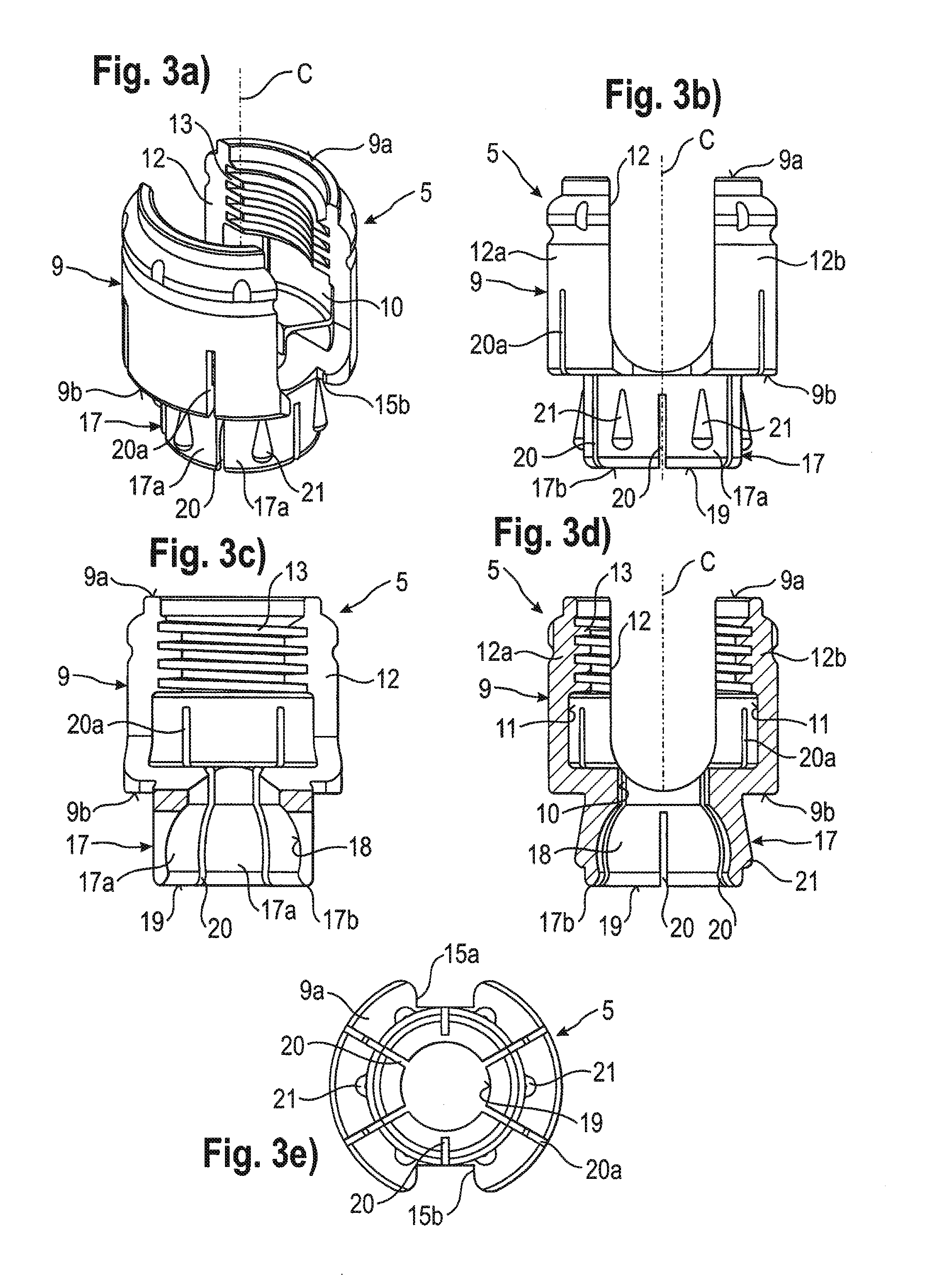
[0028]FIG. 3c is a cross-sectional view where the section is being taken in a plane containing a rod axis, and FIG. 3d is a cross-sectional view where the section is taken perpendicular to the rod axis. As shown in particular in FIGS. 1 to 3e, the receiving part body 5 includes a rod re...

second embodiment

[0048]The function and use of the bone anchoring device will now be explained with reference to FIGS. 10a to 10c. As shown in FIG. 10a, a first position of the locking ring 6′, which is the insertion position in which the locking ring 6′ is latched with respect to the receiving part body 5′, is defined in such a way that the inwardly projecting edge 610 engages or is adjacent to the groove 24 at the outer surface of the head receiving portion 17. In this condition, the head 3 can be inserted through the opening 19 into the hollow internal section 18 of the head receiving portion 17. Since the inner diameter of the inwardly projecting edge 610 is larger than the outer diameter of the groove 24, an expansion of the head receiving portion 17 when the head 3 is introduced is possible. In the first position, the locking ring 6′ may additionally be held by a clamping force between the rod receiving portion 9 and the flexible wall portions 613 of the locking ring 6′, which may be bent sli...


PUM


Abstract

A receiving part for coupling a rod to a bone anchoring element includes: a receiving part body with a rod receiving portion and a head receiving portion having an open end for introducing a head of a bone anchoring element, and a locking ring, wherein the head receiving portion includes a plurality of flexible wall portions, the flexible wall portions and the locking ring being configured to engage each other at circumferentially distinct pressure areas having positions corresponding to circumferentially separated projections on at least one of the flexible wall portions or the locking ring, and wherein the locking ring exerts a first force on at least one of the flexible wall portions at a corresponding pressure area, and exerts a second force less than the first force on the at least one flexible wall portion in a region circumferentially adjacent to the corresponding pressure area.

Description

CROSS-REFERENCE. TO RELATED APPLICATION[0001]The present application claims the benefit of U.S. Provisional Patent Application Ser. No. 61 / 421,959, filed Dec. 10, 2010, the contents of which are hereby incorporated by reference in their entirety, and claims priority to European Patent Application EP 10 194 596.2, filed Dec. 10, 2010, the contents of which are hereby incorporated by reference in their entirety.BACKGROUND[0002]1. Field of the Invention[0003]The invention relates to a receiving part for receiving a rod for coupling the rod to a bone anchoring element, and a bone anchoring device with such a receiving part. The receiving part includes a receiving part body with a rod receiving portion and a head receiving portion for receiving the head of the bone anchoring element and a locking ring for locking the head in the head receiving portion. The head can be clamped by compressing a plurality of flexible wall sections with the locking ring, where the clamping force is generated...

Claims


Application Information

Patent Timeline
Patent Type & Authority Applications(United States)
IPC IPC(8): A61B17/86A61B17/88
CPCA61B17/7037A61B17/86
Inventor BIEDERMANN, LUTZMATTHIS, WILFRIED
Owner BIEDERMANN TECH GMBH & CO KG
Why Eureka
Try Eureka