Osteosynthesis clip and insertion tool for inserting an osteosynthesis clip into bone tissue fragments

a technology of osteosynthesis and bone tissue, which is applied in the field of osteosynthesis clip and insertion tool for inserting an osteosynthesis clip into bone tissue fragments, can solve the problems of tool being incapable of engaging the stepped clip, forming gaps between the fragments, and deviating from the longitudinal axis of the bone fragments, so as to achieve minimal cutting, easy cutting through bone, and corrective positioning

Active Publication Date: 2005-12-08
MEDICREA INT SA
View PDF14 Cites 71 Cited by
  • Summary
  • Abstract
  • Description
  • Claims
  • Application Information

AI Technical Summary

Benefits of technology

[0009] It is an object of the present invention to avoid the disadvantages of known osteosynthesis clips described above. For this purpose, the present invention provides at least one surface of the engagement legs of the known clips with a threaded gripping surface substantially along an entire distance between the insertion tips and the bridging tips opposite the insertion tips. The gripping surface of the improved clip is screw-like, having an inclined thread. The thread may include a cutting edge for easily cutting through bone. Therefore, when the improved clip is inserted into the bone fragments, the threaded gripping surface extends the entire length of the engagement leg in the bone fragments. Depending on the arrangement of the thread, the amount of cutting into the bone required when removing the engagement legs therefrom would at most cut a new path in the bone for one complete turn of the leg members as opposed to past designs which required bone cutting to occur throughout the entire removal process. For example: if the engagement legs have threading completely surrounding a circumference of the engagement legs then there will be minimal cutting or possibly even no cutting of a new path when removing the legs from their bores. Also, if, for example, only one side or one edge of the legs are threaded then, at most, a new path will be cut in the bone for the duration of one complete turn of the legs upon removal.
[0010] It is another object of the present invention to provide an improved osteosynthesis clip that is manufactured, at least partially, form shape memory alloys. Shape memory alloys remain subject to physical manipulation but have the added benefit of heat induced deformation. Therefore, a clip made from shape memory alloys may be brought to its desired final position either by physical manipulation with the designed tool or by applying a heat source. The heat source can include the bone or other sources of body heat when the transition temperature is set to be at body temperature. For example, when the clip is made of a shape memory alloy having a transition temperature set to be body temperature, at surgery the clip is first cooled and reshaped to obtain the ideal shape for application: the diamond at the bridge closed widthwise, legs extending perpendicularly from the bridge and a concavity in the bridge. After the staple's legs are placed into respective bores drilled in the bone fragments to be fused together, the staple is driven deep into the bone with a percussion tool. Once the legs of the staple are in the bone, the body temperature of the bone warms the staple, reverting its shape to the original manufactured shape. A compressive force is progressively developed between the legs. At this point, if there has been too much compression and the insertion tips of the legs have bent away from each other, corrective positioning can be achieved by applying an upward force to the depression in the bridge with the insertion tool. Proper planning and selection of a clip with a final shape which will compress the same distance as the gap between bone fragments may also avoid the need for additional use of tools and corrective measures.
[0011] It is another object of the present invention to provide an improved insertion tool to insert an osteosynthesis clip into bone fragments. The improved tool incorporates an adjustable member configurable to contact the bridging portions of the clip. This contact is necessary to insert the clip into bores drilled for receiving the engagement legs and for applying the third force opposite to the second force applied to the non-linear deformable region. By incorporating the adjustable member to the improved tool, it is capable of correctly applying the third force to the bridge member of a stepped clip having a shape exemplified in FIGS. 4a and 4b of the '600 App. and can be easily reconfigured to also engage and apply the third force to the bridge at points nearest the respective bridging portions of a non-stepped (“U”-shaped) clip as shown in FIGS. 1 and 2 of the '600 App.

Problems solved by technology

This pressure differential may cause the bone tissue fragments to pivot toward the bridge of the clip, thereby causing a deviation of the longitudinal axis of the bone fragments and the formation of a gap between the fragments, especially nearest the insertion tips of the engagement legs.
However, the legs may pivot in such a way that a gap may be formed at the portion of the fracture opposite the clip.
As will be shown herein, the tool is incapable of engaging the stepped clip in a stepped down region in order to apply the third force at that region and thereby can not effectively counter the second force applied to the non-linear deformable region.
It has further been found that the known removal procedures of a clip from the bone fragments can cause excessive damage to the bone fragments.
Also, such a direct linear removal of the clip often requires insertion of a lever between the clip's bridge and the bone surface to pry the clip from the bone.
The traction forces associated with such removal procedures causes the retaining teeth to tear the original bony channel as they exit the bone, causing trauma.
Moreover, such traction forces can further damage the bone by causing splints or fractures and can further thwart the intended healing process by causing undesired displacement of the bone fragments.
These heat-initiated changes cause gross changes in the shape of the implant formed from memory metal.

Method used


Image

  • Osteosynthesis clip and insertion tool for inserting an osteosynthesis clip into bone tissue fragments
  • Osteosynthesis clip and insertion tool for inserting an osteosynthesis clip into bone tissue fragments
  • Osteosynthesis clip and insertion tool for inserting an osteosynthesis clip into bone tissue fragments

Examples


Embodiment Construction

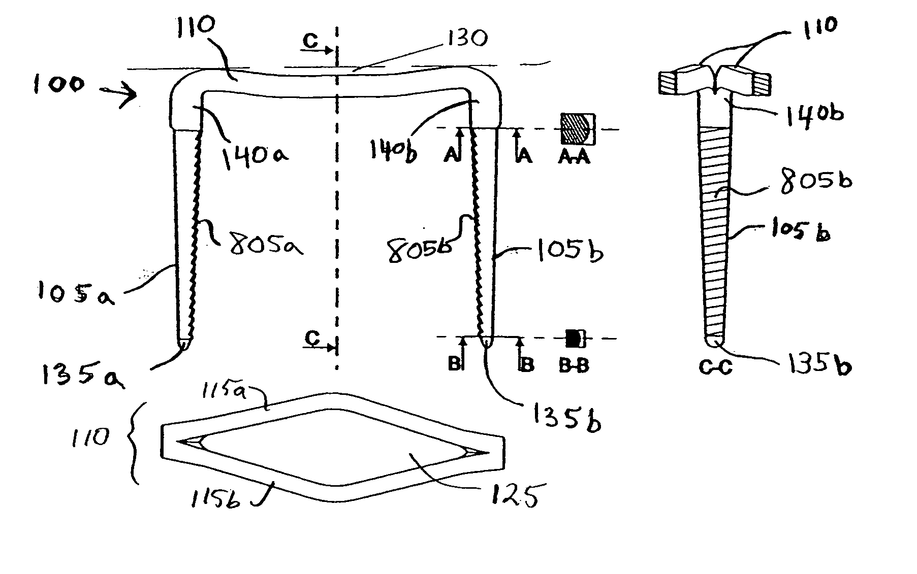
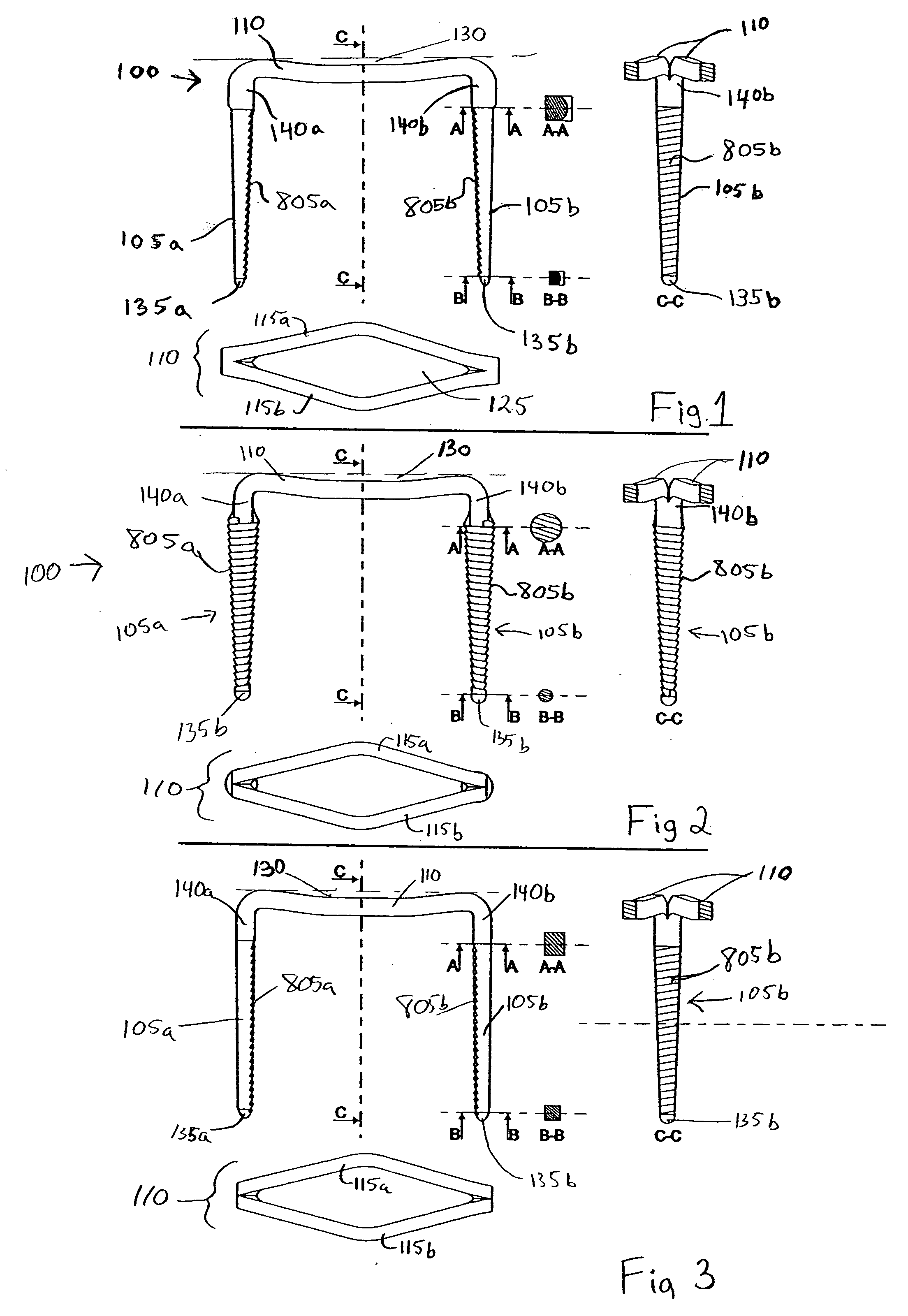
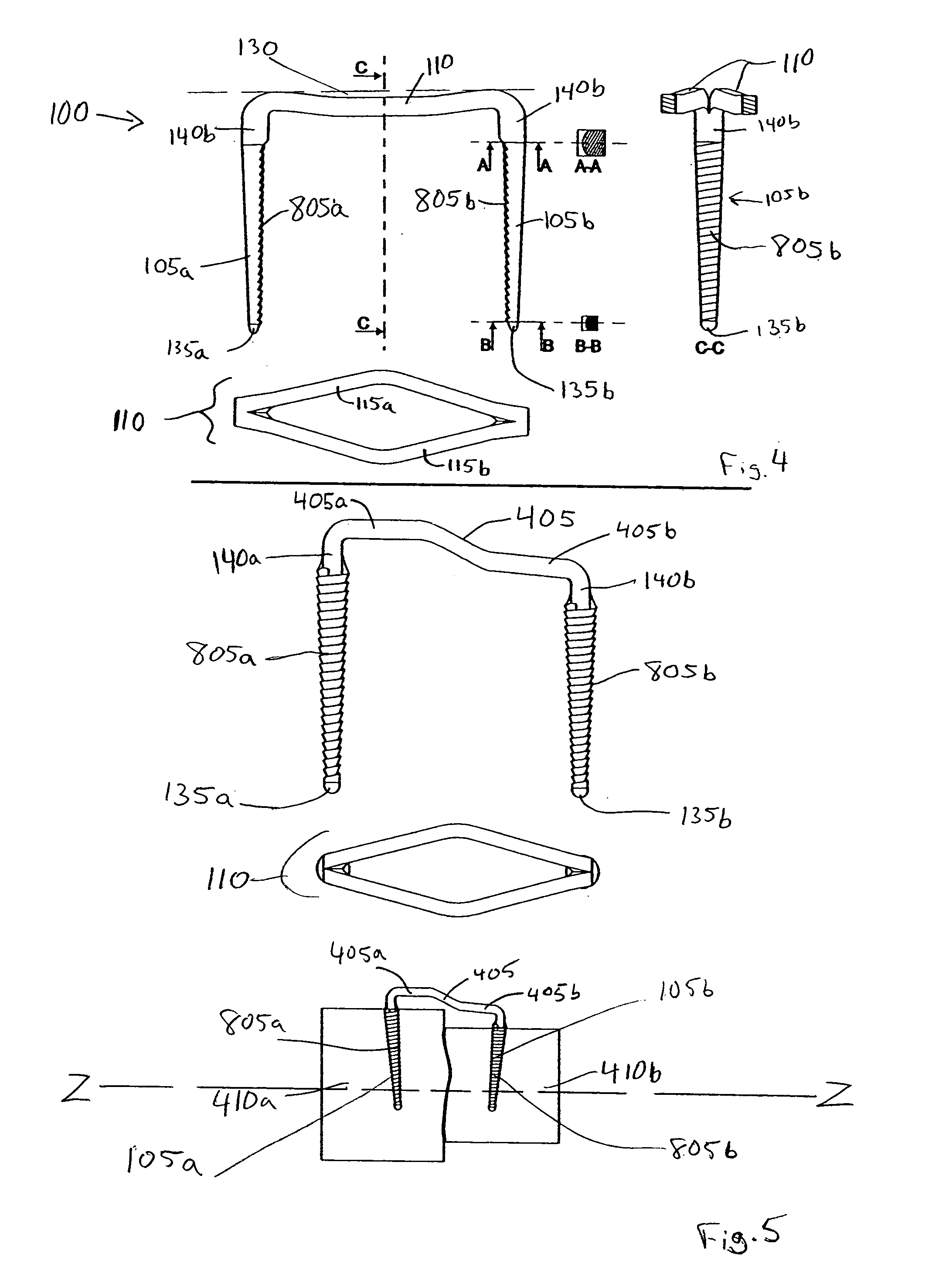
[0022] To the extent that the elements of the invention match those represented in the '600 App., the reference numerals will remain the same. Referring now to FIG. 1, there are seen side, top and a cross sectional views along drawn lines “A-A”, “B-B” and “C-C”, respectively, of a first exemplary improved, elastic, osteosynthesis clip 100 according to the present invention. Clip 100 includes at least two engagement legs 105a and 105b and a connecting bridge 110 to couple engagement legs 105a, 105b to one another, thereby forming a unitary clip 100. Engagement legs 105a, 105b extend approximately parallel to one another and include respective insertion tips 135a, 135b, shown to be rounded, for insertion into the bone tissue and respective bridging tips 140a, 140b coupled to bridge 110. A taper may be provided in the engagement legs 105a, 105b by having a linear decrease in cross sectional area along the distance between the bridging tips 140a, 140b to respective insertion tips 135a, ...


PUM


Abstract

An improved osteosynthesis clip for the cicatrization of bone fragments, an improved insertion tool and method for inserting the improved clip and a surgical system implementing the improved clip and insertion tool are provided. The clip includes at least two engagement legs extending approximately parallel to one another and including insertion tips to be inserted into the bone tissue fragments; and a connecting bridge coupled to the at least two engagement legs at portions opposite the insertion portions, the connecting bridge including at least two elongated sections extending along side one another, the elongated sections extending along a non-linear trajectory to form a non-linear deformable region, such as a depression or a dome, wherein the engagement legs having respective helical screw surfaces extending substantially an entire distance between respective insertion and opposite portions to facilitate removal of the clip after the bone tissue fragments have fused. The improved clip may be made of any biocompatible material, including shape memory alloys, such as Nitinol. The insertion tool is improved to apply force at the bridging tips of either a stepped on a non stepped clip.

Description

RELATED APPLICATION DATA [0001] The present application is a continuing application, claiming the benefit of co-pending parent application Ser. No. 10 / 634,410 filed on Aug. 5, 2003, published Mar. 3, 2005 and entitled “OSTEOSYNTHESIS CLIP AND INSERTION TOOL FOR INSERTING AN OSTEOSYNTHESIS CLIP INTO BONE TISSUE FRAGMENTS”, Publication No. 2005 / 0049600 (hereinafter the “'600 App.”) the entire contents of which are expressly incorporated herein by reference.FIELD OF THE INVENTION [0002] The present invention relates to an improved osteosynthesis clip having improved structural properties and an improved apparatus and method for inserting and removing the osteosynthesis clip into and from bone tissue fragments, and having an improved insertion tool for inserting the osteosynthesis clip into bone tissue fragments. BACKGROUND INFORMATION [0003] There are various known elements (e.g., casts and internal elements, such as screws, plates, clips, etc.) and methods for permitting the cicatriza...

Claims


Application Information

Patent Timeline
Patent Type & Authority Applications(United States)
IPC IPC(8): A61B17/068A61B17/68A61B17/064A61B17/88
CPCA61B17/0642A61B17/0644A61B17/0682A61B17/68A61B17/8872A61B2017/0648
Inventor GROISO, JORGE A.
Owner MEDICREA INT SA
Why Eureka
Try Eureka