
Bearing device for wheel, and axle module

A bearing device and wheel technology, applied to bearings, axles, wheels, etc., can solve the problems of poor management of parts, deterioration of operability, and large number of parts, and achieve the effect of preventing friction and damage

Active Publication Date: 2010-08-11
NTN CORP
View PDF1 Cites 8 Cited by
  • Summary
  • Abstract
  • Description
  • Claims
  • Application Information

AI Technical Summary

Problems solved by technology

Therefore, screw tightening work is required during assembly, and operability is deteriorated, and the number of parts is also large, and parts management is also poor.

Method used


Image

  • Bearing device for wheel, and axle module
  • Bearing device for wheel, and axle module
  • Bearing device for wheel, and axle module

Examples


Embodiment

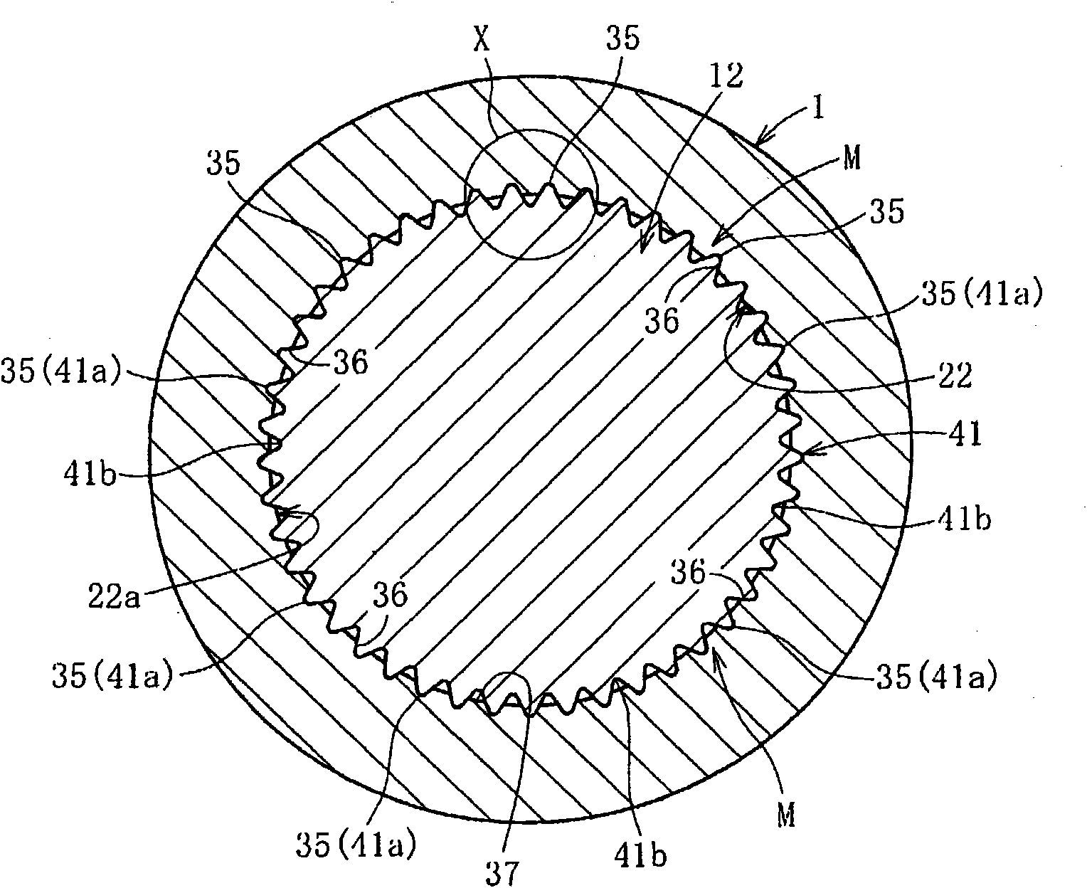
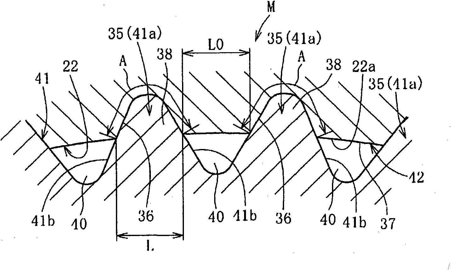
[0283] The relationship between the hardness difference between the convex portion 35 and the concave portion formation portion and the press-fitting load was investigated, and the results are shown in Figure 31 . In this case, a male spline having a modulus of 0.48 and a number of teeth of 59 is formed on the shaft portion 12 , and the male spline is pressed into the hole portion 22 of the hub wheel 1 . In addition, the diameter difference between the outer diameter of the shaft portion 12 and the inner diameter of the hole portion 22 of the hub ring 1 is Δd, and the height of the convex portion is H. When the ratio is Δd / 2h, 0.3<Δd / 2h< 0.86.

[0284] According to the Figure 31 It can be seen that when the difference in hardness is less than 20HRC, the indentation load is large and so-called cracking occurs.


PUM

PropertyMeasurementUnit
Hardnessaaaaaaaaaa
Hardnessaaaaaaaaaa
Surface hardnessaaaaaaaaaa

Abstract

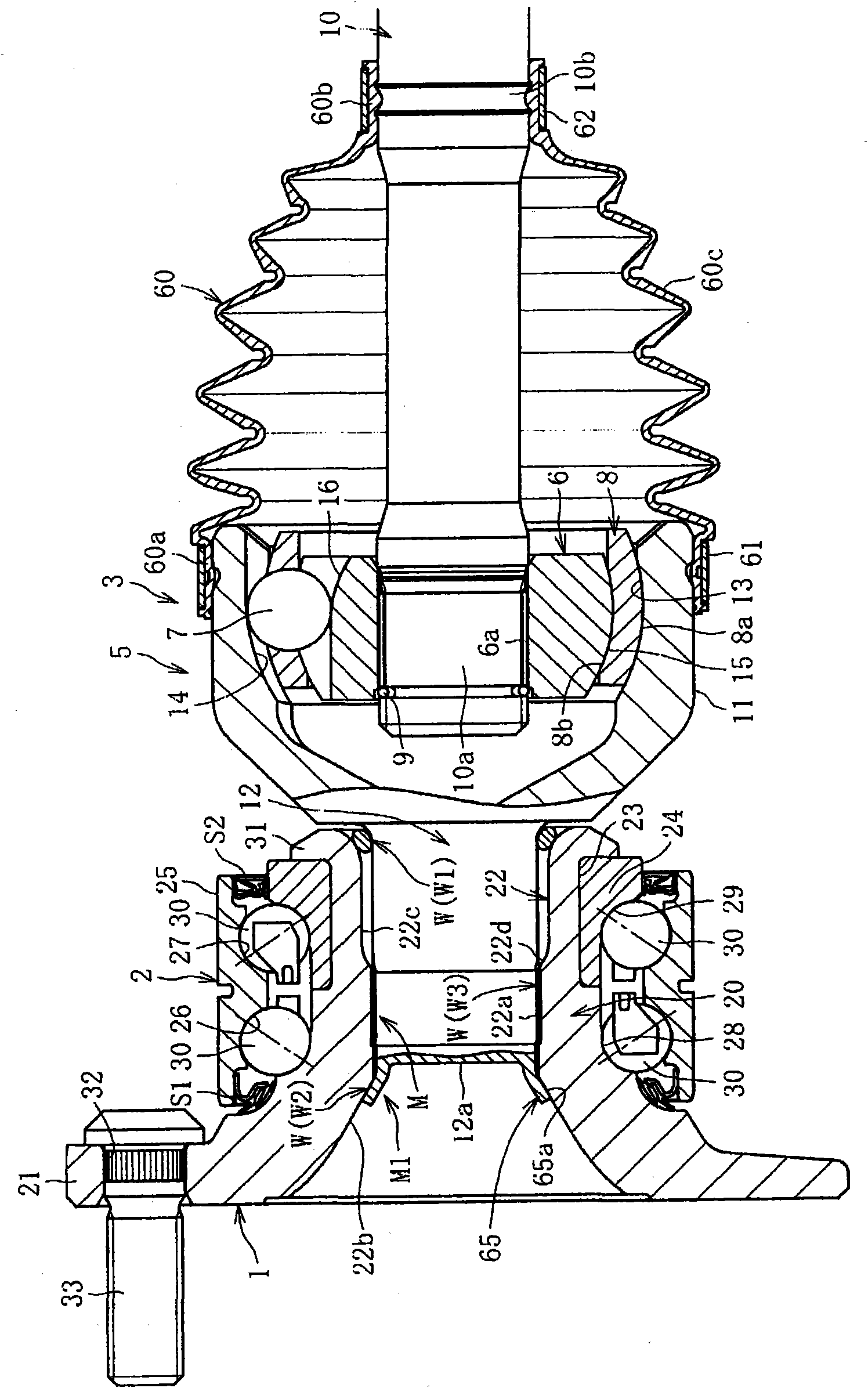
Provided are a bearing device for a wheel, in which circumferential play is reduced, which provides excellent workability in connection between a hub ring and an outer joint member of a constant velocity universal joint, in which fitting between the hub ring and the outer joint member of the constant velocity universal joint is stable, and which has excellent strength, and an axle module using the bearing device. An axially extending projection is formed on either of the outer diameter surface of a shaft section of the outer joint member and the inner diameter surface of a hole of the hub ring. The projection is press-fitted to the other in the axial direction to form a recess in the other by the press-fitting. By this, a recess / projection fit structure is formed, in which the entire regions of those portions of the projection and the recess at which they are fitted to each other are in intimate contact with each other. The hardness of at least that portion of the projection at which the press-fit starts is higher than that of a portion where the recess is formed. The difference in hardness in HRC is 20 or more.

Description

technical field [0001] The present invention relates to a wheel bearing device for supporting a wheel rotatably with respect to a vehicle body of a vehicle such as an automobile, and an axle module using such a wheel bearing device. Background technique [0002] The wheel bearing device has evolved from the so-called first-generation structure that uses multiple rows of rolling bearings alone to the second-generation that has a body mounting flange integrally on the outer member, and has developed a wheel hub ring that has a wheel mounting flange integrally. The outer circumference of the third generation of the inner rolling surface is integrally formed on one side of the multi-row rolling bearing. In addition, the constant velocity universal joint is integrally formed on the hub ring, and the outer circumference of the outer joint part constituting the constant velocity universal joint is developed. The fourth generation of the other inner rolling surface of the multi-row ...

Claims


Application Information

Patent Timeline
IPC IPC(8): F16C35/063B60B35/14B60B35/18F16C19/18F16C33/62F16D1/06F16D3/20
CPCF16C19/186B60B27/00F16D2300/10F16C2326/02F16D3/2237F16C35/0635F16C33/64F16D2003/22326F16D1/072F16C19/184F16C2202/04F16C33/586F16D1/108F16D2001/103F16D2250/0053B60B27/0005
Inventor 小泽仁博浅野祐一黑田正幸中川亮山内清茂梅木田光
Owner NTN CORP
Learn More