Eureka AIR delivers breakthrough ideas for toughest innovation challenges, trusted by R&D personnel around the world.

Method and system for calibrating an estimated clutch characteristic curve

Inactive Publication Date: 2014-10-30
VOLVO LASTVAGNAR AB
View PDF2 Cites 7 Cited by
  • Summary
  • Abstract
  • Description
  • Claims
  • Application Information

AI Technical Summary

Benefits of technology

The patent text describes a calibration method for a dual-clutch transmission that removes the disadvantages of previous methods, such as being influenced by external factors and wearing of the clutches. The method uses a calibration system that is executed with the transmission output shaft disengaged from the clutch input shaft, resulting in accurate calibration results. The method can calibrate both small, medium, and high torque transmission capabilities, as well as the entire range of the clutch characteristic curve. Additionally, the method can calibrate both friction clutches simultaneously, reducing wear and tear on the clutches. The method also includes a step to wait for the second friction clutch to stabilize before calculating its torque transmission capability. Overall, this patent text describes a more efficient and accurate calibration method for dual-clutch transmissions.

Problems solved by technology

This calibration method however has several disadvantageous.
Unintentional engagement of the gear in question can occur in case of interconnection of the tooth-clutch.

Method used


Image

  • Method and system for calibrating an estimated clutch characteristic curve
  • Method and system for calibrating an estimated clutch characteristic curve
  • Method and system for calibrating an estimated clutch characteristic curve

Examples


first embodiment

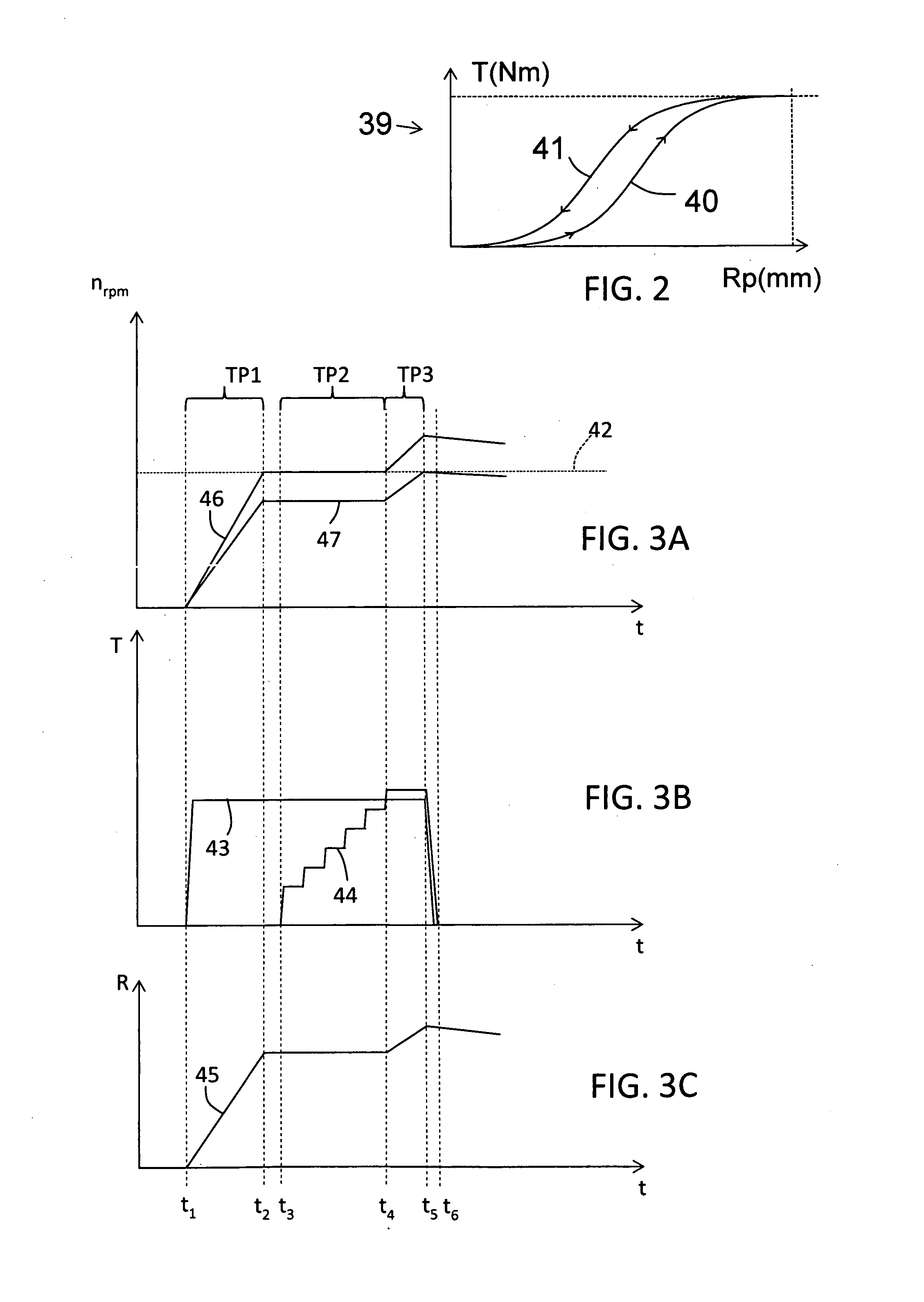
[0038]FIG. 3A to 3C disclose a first control alternative of the aspect of the invention. The first control alternative calibrates a hysteresis engagement branch 40 of the clutch characteristic curve 39 of the second friction clutch 10, wherein all plotted diagrams having different clutch characteristics on their Y-axis during the same time interval t1-t6 on their X-axis.

[0039]In FIG. 3A, the Y-axis corresponds to rotation speed nrpm, in FIG. 3B, the Y-axis corresponds to torque transmission capability of the first and second friction clutches 9, 10, and in FIG. 3C, the Y-axis corresponds to a ratio between a rotational speed of said clutch input shaft 7 and a rotational speed of any of the first input shaft 12, the second input shafts 13, or the countershaft 17. The X-axis corresponds to time t.

[0040]The prime mover of the vehicle is operated with constant speed and the clutch input shaft speed 42 is thus constant. At time t1, a regulating parameter of the first clutch regulator is ...

second embodiment

[0055]Thereafter, a regulating parameter of the first clutch regulator is controlled such that the first friction clutch 9 is fully engaged to provide maximal torque transmission capability. Subsequently, after synchronisation of the first friction clutch 9 with the clutch input shaft 7 has been obtained, the second friction clutch 10 is being engaged, and the torque transmission capability of the second friction clutch 10 is calculated based on an estimated and / or measured output torque of said prime mover, and said known gear ratio. Preferably, for the purpose of obtaining improved accuracy, also the friction losses within the transmission 1 are included in the calculation. Equation 2 below is preferably used for calculating the torque transmission capability of the second friction clutch 10

TC2=TEiP1+TDRAGiP1-iP2Equation2

[0056]where

TC2 denotes torque transmission capability of the second friction clutch 10;

TE denotes engine output torque;

TDRAG denotes frictional losses induced mai...


PUM


Abstract

A method and a system for calibrating an estimated clutch characteristic curve of a dual-clutch vehicle transmission are provided. The method includesmechanically interconnecting a first input shaft with a second input shaft, whereby a transmission output shaft is disengaged;controlling,according to a first alternative, a regulating parameter of a first clutch regulator such that a first friction clutch is engaged with a first torque transmission capability, that a second friction clutch (initially is disengaged, and subsequently engaged; oraccording to a second alternative, that the second friction clutch is initially engaged, a regulating parameter of the first clutch regulator such that the first friction clutch is engaged with a first torque transmission capability, and that the second friction clutch subsequently disengaged;calculating a torque transmission capability of the second friction clutch; and adjusting an estimated clutch characteristic curve of the second friction clutch.

Description

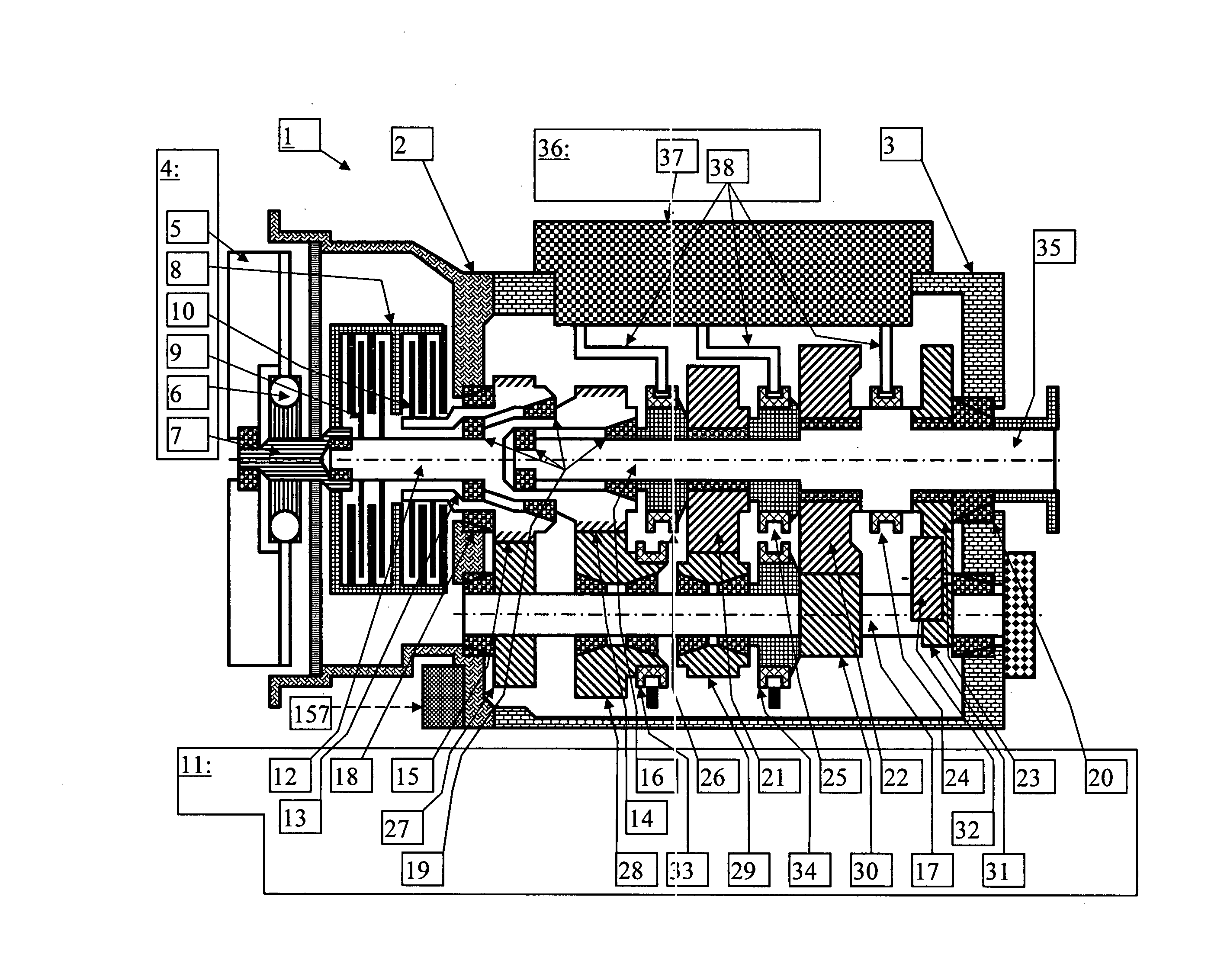
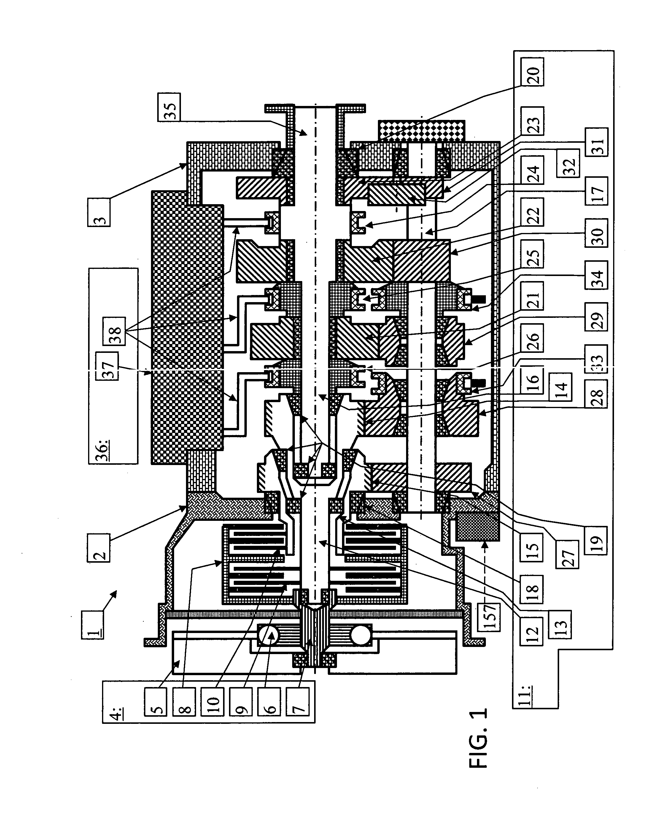
BACKGROUND AND SUMMARY[0001]The present invention relates, according to an aspect thereof, to a method and system for calibrating an estimated clutch characteristic curve of a dual-clutch assembly of a transmission for a motor vehicle, wherein said transmission comprising a dual-clutch assembly with a first friction clutch, a first clutch regulator, a second friction clutch, and a second clutch regulator, each of said friction clutches being drivingly connected to a prime mover by means of a clutch input shaft, a first input shaft connected to said first friction clutch, a second input shaft connected to said second friction clutch, at least one countershaft arranged parallel with at least one of said first and second input shafts, gearwheels, tooth clutches, and a transmission output shaft, whereby selective engagement of said first and second frictional clutches and tooth clutches, different speed ratios between said clutch input shaft and said transmission output shaft can be est...

Claims


Application Information

Patent Timeline
IPC IPC(8): F16D48/06
CPCF16D48/06F16D2500/1086F16D2500/30415F16D2500/30426F16D2500/3067F16D2500/30803F16D2500/50236F16D2500/506
Inventor KARPENMAN, FREDRIKRAZAZNEJAD, BEHROOZRYBERG, HENRIKAHO, SAMISJOQVIST, FREDRIK
Owner VOLVO LASTVAGNAR AB
Why Eureka
Eureka Blog
Learn More