Metal Annulus Seal

Active Publication Date: 2010-05-13
VETCO GRAY
View PDF5 Cites 73 Cited by
  • Summary
  • Abstract
  • Description
  • Claims
  • Application Information

AI Technical Summary

Benefits of technology

[0010]The combination of stored energy provided for by the energizing rings, the locking mechanisms of the seal ring and the energizing ring, and the compliant soft outer inserts, provides gas tight

Problems solved by technology

A reduction in axial force on the energizing ring results in a reduction in the radial inward and outward forces on the inner and outer walls of the seal ring

Method used


Image

  • Metal Annulus Seal
  • Metal Annulus Seal
  • Metal Annulus Seal

Examples


Example

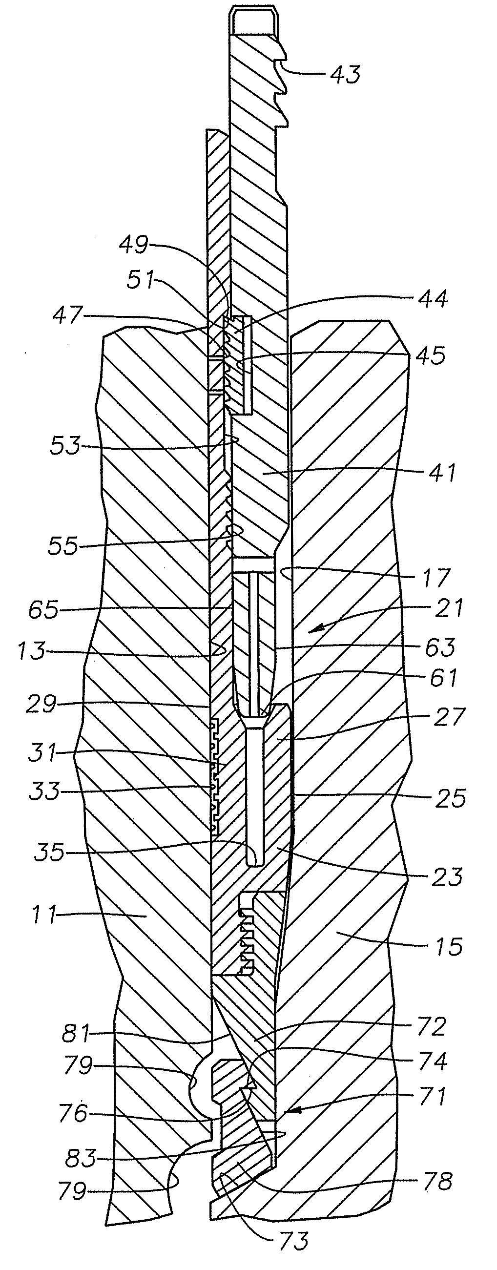
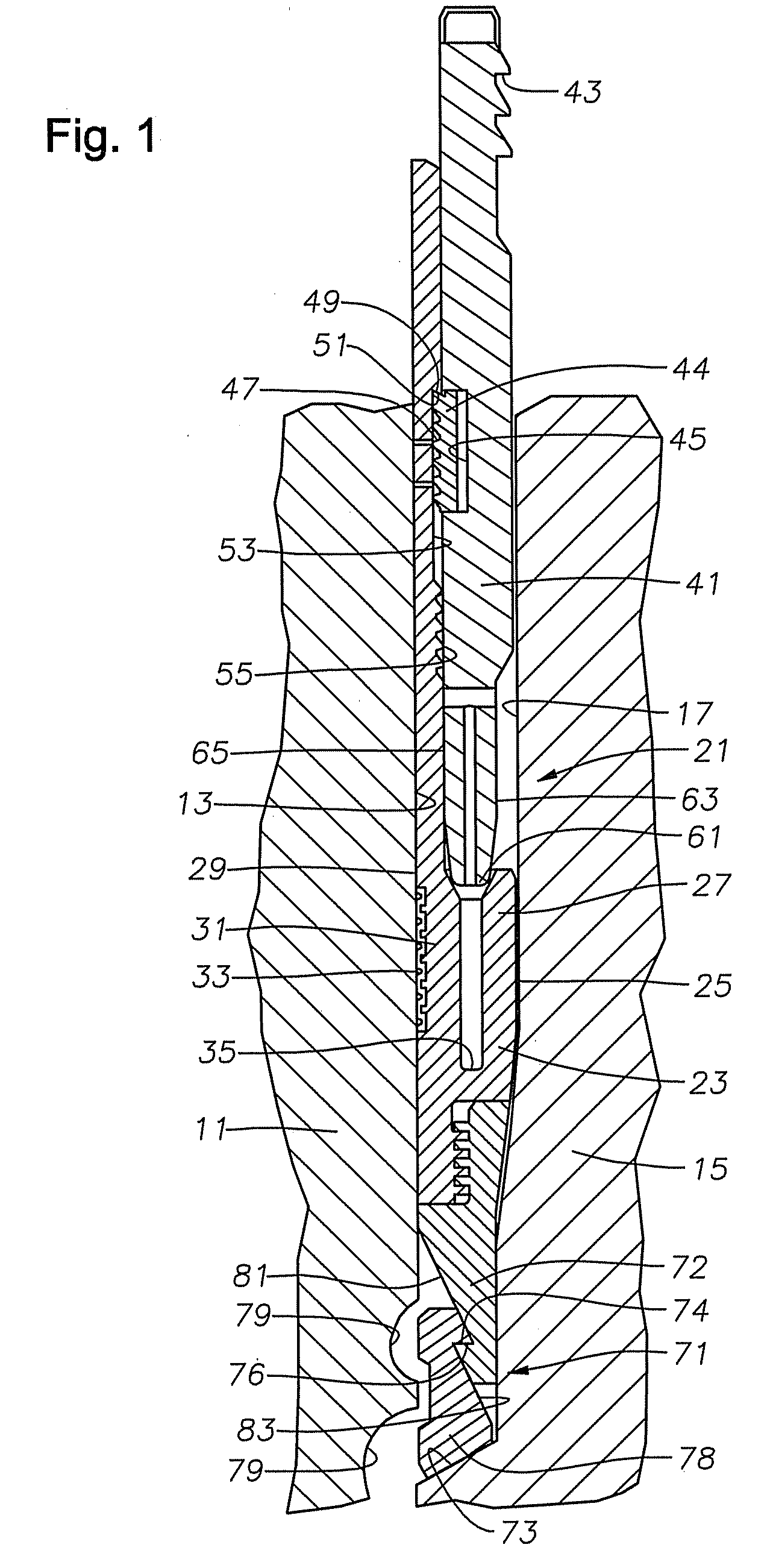
[0015]Referring to FIG. 1, a portion of a high pressure wellhead housing 11 is shown. Housing 11 is located at an upper end of a well and serves as an outer wellhead member in this example. Housing 11 has a bore 13 located therein.

[0016]In this example, the inner wellhead member comprises a casing hanger 15, which is shown partially in FIG. 1 within bore 13. Alternately, wellhead housing 11 could be a tubing spool or a Christmas tree. Alternately, casing hanger 15 could be a tubing hanger, plug, safety valve or other device. Casing hanger 15 has an exterior annular recess radially spaced inward from bore 13 to define a seal pocket 17.

[0017]A metal-to-metal seal assembly 21 is located in seal pocket 17. Seal assembly 21 includes a seal ring 23 formed of a metal such as steel. Seal ring 23 has an inner wall 25 comprised of inner seal leg 27 for sealing against the cylindrical wall of seal pocket 17. Seal ring 23 has an outer wall surface 29 comprised of outer seal leg 31 that seals ag...


PUM


Abstract

A wellhead seal assembly forms a metal-to-metal seal between inner and outer wellhead members. A metal seal ring has inner and outer walls separated by a slot. An energizing ring has a C-ring captured on its outer surface. When the energizing ring is moved farther into the slot, the C-ring is forced from its pocket and engages a profile on the seal ring, locking the energizing ring to the seal assembly.

Description

FIELD OF THE INVENTION [0001]This invention relates in general to wellhead assemblies and in particular to a seal for sealing between inner and outer wellhead members.BACKGROUND OF THE INVENTION [0002]Seals are used between inner and outer wellhead tubular members to contain internal well pressure. The inner wellhead member may be a tubing hanger that supports a string of tubing extending into the well for the flow of production fluid. The tubing hanger lands in an outer wellhead member, which may be wellhead housing, a Christmas tree, or tubing head. A packoff or seal seals between the tubing hanger and the outer wellhead member. Alternately, the inner wellhead member might be a casing hanger located in a wellhead housing and secured to a string of casing extending into the well. A seal or packoff seals between the casing hanger and the wellhead housing.[0003]A variety of seals of this nature have been employed in the prior art. Prior art seals include elastomeric and partially met...

Claims


Application Information

Patent Timeline
IPC IPC(8): E21B33/12
CPCE21B33/04E21B2033/005E21B2200/01
Inventor NELSON, JOHN E.
Owner VETCO GRAY
Why Eureka
Try Eureka