Eureka AIR delivers breakthrough ideas for toughest innovation challenges, trusted by R&D personnel around the world.

Optical inspection equipment

A technology of optical detection and equipment, applied in the field of substrate processing, can solve problems such as misjudgment of AOI equipment

Active Publication Date: 2014-02-05
HEFEI BOE OPTOELECTRONICS TECH +1
View PDF7 Cites 5 Cited by
  • Summary
  • Abstract
  • Description
  • Claims
  • Application Information

AI Technical Summary

Problems solved by technology

[0004] However, during the optical detection process of the above-mentioned traditional AOI equipment on the substrate carried by the robot arm, since the surface of the substrate may be attached with fine particles such as dust, this leads to misjudgment of the AOI equipment.

Method used


Image

  • Optical inspection equipment
  • Optical inspection equipment
  • Optical inspection equipment

Examples


Embodiment Construction

[0036] The specific implementation manners of the present invention will be further described in detail below in conjunction with the accompanying drawings and embodiments. The following examples are used to illustrate the present invention, but are not intended to limit the scope of the present invention.

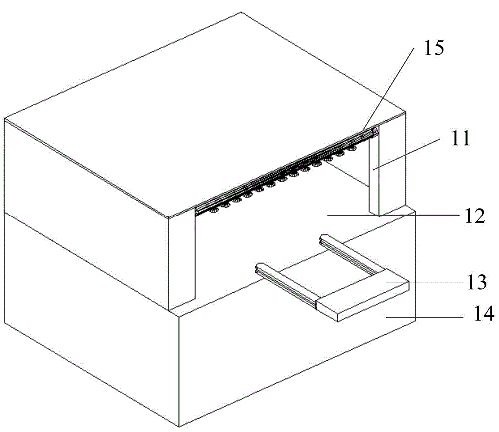
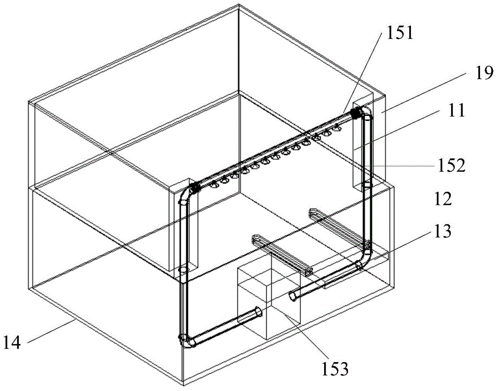
[0037] An embodiment of the present invention provides an optical detection device, the structure schematic diagram is as follows figure 2 As shown, the optical detection equipment includes a detection machine 12, the detection machine 12 is provided with a detection cavity, and also includes a dust removal device 15, and the dust removal device 15 is arranged at the equipment entrance and exit 11 of the detection cavity . figure 2 A robot arm 13 may also be provided at the position where the detection machine 12 is close to the equipment entrance 11 , for carrying the substrate to be tested (hereinafter referred to as the substrate) into and out of the detection chambe...


PUM


Abstract

The invention discloses optical inspection equipment which comprises an inspection table with an inspection cavity body, and a dust collector at an equipment passageway of the inspection cavity body. According to the optical inspection equipment, the dust collector is added to the equipment passageway, through which a base plate goes in and out of the inspection table, and the base plate can be subjected to dust collection in a whole-body scanning manner through the dust collector when entering the inspection table through the equipment passageway, so that a good cleaning effect on the surface of the base plate is achieved, and the problem of misjudgment of an optical inspection result caused by small particles such as dust remained on the surface of the base plate due to a poor cleaning effect in a process of optically inspecting the surface of the base plate by the optical inspection equipment is solved. Due to the optical inspection equipment, the surface of the base plate can be subjected to dust collection in real time by the dust collector before the base plate is optically inspected, thereby avoiding misjudgment caused by remained particles.

Description

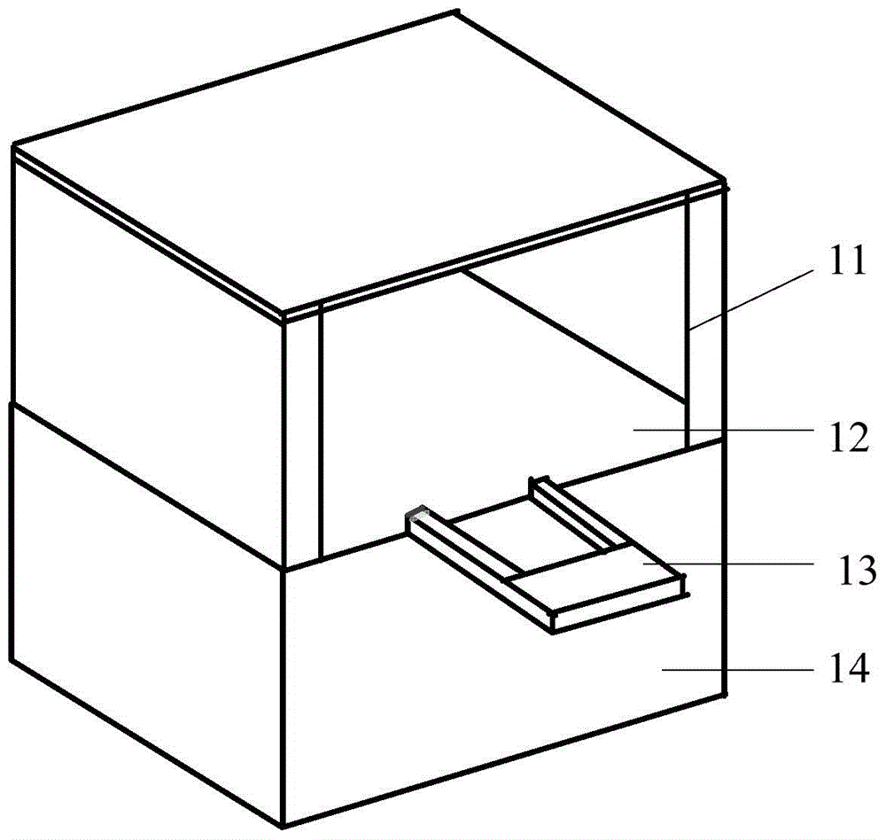
technical field [0001] The invention relates to the field of substrate processing, in particular to an optical detection device. Background technique [0002] AOI (Automated Optical Inspection) is based on optical principles, using high-speed and high-precision visual processing technology to automatically detect various mounting errors on PCB (Printed Circuit Board, printed circuit board) and common defects encountered in welding production Equipment for testing. [0003] The structure diagram of traditional AOI equipment is as follows: figure 1 As shown, 11 is the equipment entrance and exit, 12 is the testing machine, 13 is the mechanical arm, 14 is the bottom box, figure 1 The arrow in is pointing to the moving direction of the substrate when it enters the testing machine 12 from the equipment entrance 11 . The AOI equipment can realize the automatic detection of PCB board. When the AOI equipment automatically detects the PCB board, it automatically scans the PCB boa...

Claims


Application Information

Patent Timeline
IPC IPC(8): G01N21/956B08B15/04
Inventor 郑恒
Owner HEFEI BOE OPTOELECTRONICS TECH
Why Eureka
Eureka Blog
Learn More