Optical waveguide pulse coupler and manufacturing method thereof

A technology of pulse coupling and optical waveguide, applied in the field of integrated optics and optical waveguide

Inactive Publication Date: 2014-02-05
UNIV OF SHANGHAI FOR SCI & TECH
View PDF4 Cites 5 Cited by
  • Summary
  • Abstract
  • Description
  • Claims
  • Application Information

AI Technical Summary

Problems solved by technology

The work results of realizing the pulse-coupled dynamic process required by PCNN by using the all-optical method have not been reported so far

Method used


Image

  • Optical waveguide pulse coupler and manufacturing method thereof
  • Optical waveguide pulse coupler and manufacturing method thereof
  • Optical waveguide pulse coupler and manufacturing method thereof

Examples


Embodiment Construction

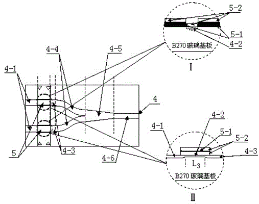
[0031] The basic structure of the core optical path of the optical waveguide pulse coupler is as follows: figure 1 As shown, it consists of an inverted Y-branch waveguide 4 and two composite waveguides 5 symmetrically prepared at the two branch positions of the inverted Y-branch waveguide 4. The inverted Y-branch waveguide 4 is prepared on the upper surface of a glass substrate. The glass substrate can be glass such as B270, or optical glass such as BK7 or K9. The Y-branch waveguide 4 consists of two input straight waveguides 4-1 with a length of 5 mm, two cut-off straight waveguides 4-2, two transfer straight waveguides 4-3, two curved waveguides 4-4, and a wedge-shaped transition waveguide 4- 5 and an output straight waveguide 4-6 are sequentially and symmetrically connected in a Y shape. The widths of two input straight waveguides 4-1, two cutoff straight waveguides 4-2, two transfer straight waveguides 4-3, two curved waveguides 4-4 and one output straight waveguide 4-6 a...


PUM


Abstract

The invention relates to an optical waveguide pulse coupler and a manufacturing method thereof. The unsaturation light blocking effect of As2S8-B270 glass composite waveguide is used for achieving coupling response on input effect electric pulse signals, and an optics reversal phase asymmetric input waveguide branch mode coupling effect is used for providing threshold value limitation. The optics corpuscular property shown by the unsaturation light blocking effect and the optics undulatory property shown by branch waveguide mode coupling are combined in an organic mode on an optical waveguide carrier, a full-optical mode is used for achieving a pulse coupling kinetics process between input effect electric pulses and output synchronization electric pulses, and a full-optical method is used for achieving the pulse coupling kinetics process which meets the requirement of a pulse coupled neural network (PCNN).

Description

technical field [0001] The invention relates to an integrated optics and optical waveguide technology, in particular to an optical waveguide pulse coupler and a manufacturing method thereof. Background technique [0002] The non-linear accumulation and leakage in response to external pulse stimulation signals is a characteristic requirement of pulse-coupled neural network (PCNN) for imitation neurons. The state is manifested as a synchronous release of response pulses, and below the threshold it shows silence. The coupling dynamics between the input pulse and the output pulse is based on the experimental basis of the study of the visual cortex of the biological brain, and PCNN provides a promising way for the development of a more accurate bionic visual system. Although there are many software implementation methods of PCNN, the real-time response operation of PCNN needs to be realized by hardware. In terms of hardware implementation, reported circuit technologies include ...

Claims


Application Information

Patent Timeline
Patent Type & Authority Applications(China)
IPC IPC(8): G02B6/255G02B6/125G02B6/134
Inventor 陈抱雪周建忠李家韡
Owner UNIV OF SHANGHAI FOR SCI & TECH
Why Eureka
Try Eureka