
Fault detection method and device

A technology of fault detection and fault point, which is applied in the field of communication, can solve problems such as inability to locate faults, affect system performance, and aging of pigtails, and achieve the effects of improving troubleshooting speed, improving system performance, and reducing maintenance costs

Inactive Publication Date: 2016-08-24
HUAWEI TECH CO LTD
View PDF5 Cites 0 Cited by
  • Summary
  • Abstract
  • Description
  • Claims
  • Application Information

AI Technical Summary

Problems solved by technology

[0004] Since the MUX and DEMUX are passive, fault location cannot be performed, and due to the large number of optical module interfaces, the probability of faults such as dirty interfaces and pigtail aging is relatively high. It is necessary to check every possible fault location, the operation is cumbersome, and the time required for troubleshooting is too long, which affects the system performance

Method used


Image

  • Fault detection method and device
  • Fault detection method and device
  • Fault detection method and device

Examples


Embodiment Construction

[0056] The following will clearly and completely describe the technical solutions in the embodiments of the present invention with reference to the accompanying drawings in the embodiments of the present invention. Obviously, the described embodiments are some of the embodiments of the present invention, but not all of them. Based on the embodiments of the present invention, all other embodiments obtained by persons of ordinary skill in the art without making creative efforts belong to the protection scope of the present invention.

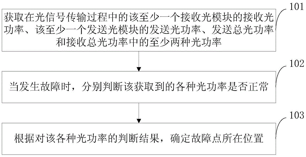
[0057] figure 1 It is a flowchart of a fault detection method provided by an embodiment of the present invention. The fault detection method is used in a multiplexer / demultiplexer system, and the multiplexer / demultiplexer system includes at least one transmitting optical module, at least one receiving optical module, and a multiplexer MUX, Wave Demultiplexer DEMUX, see figure 1 , the method includes:

[0058] 101. Acquire at least two optical po...


PUM


Abstract

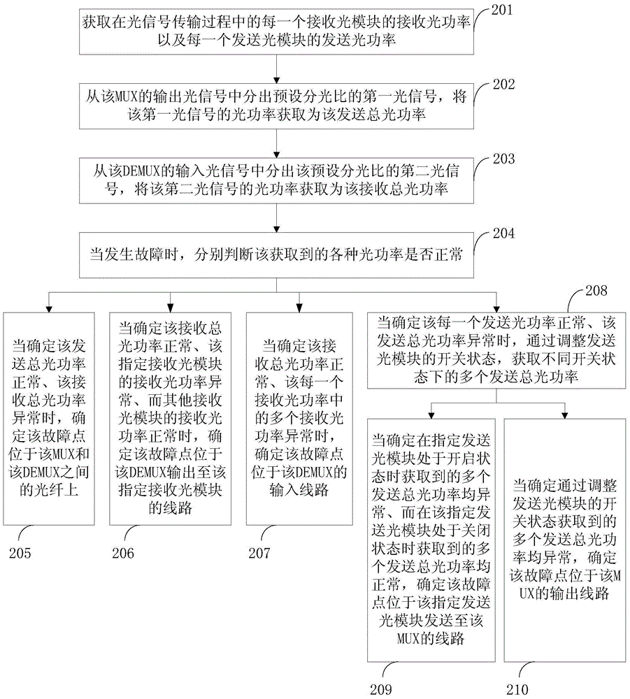
The invention discloses a fault detection method and device, belonging to the technical field of communication. The method is used in a wavelength multiplexing and demultiplexing system, and the method includes: acquiring the received optical power of the at least one receiving optical module, the transmitting optical power of the at least one transmitting optical module, and the total transmitting optical power during optical signal transmission. Power and at least two optical powers in the total received optical power; when a fault occurs, respectively judge whether the obtained various optical powers are normal; according to the judgment results of the various optical powers, determine the location of the fault point . When a fault occurs, the present invention determines the location of the fault point by judging whether the various optical powers obtained are normal, solves the problem that passive equipment cannot perform fault location, realizes automatic fault location, and greatly reduces The workload is reduced, the maintenance cost is reduced, the troubleshooting speed is improved, and the system performance is improved.

Description

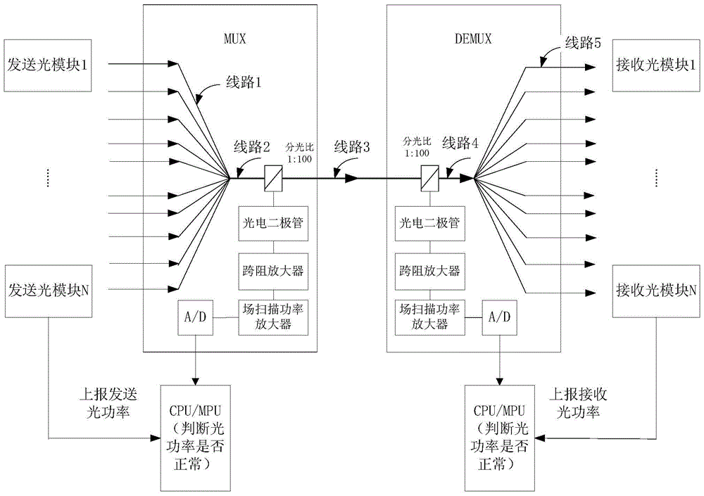
technical field [0001] The invention relates to the field of communication technology, in particular to a fault detection method and device. Background technique [0002] In a network using multiplexing and demultiplexing systems, multiple WDM (Wavelength Division Multiplexing, wavelength division multiplexing) optical modules can be used to combine optical signals of different wavelengths through MUX (Multiplexing, multiplexer) (multiplexing) wave), and transmit it through an optical fiber, and then separate (demultiplex) the optical signals of different wavelengths in the transmitted signal through DEMUX (De Multiplexing) to realize the coupling of optical signals of different wavelengths to the same optical fiber for transmission purposes. [0003] In the process of realizing the present invention, the inventor finds that there are at least the following problems in the prior art: [0004] Since the MUX and DEMUX are passive, fault location cannot be performed, and due ...

Claims


Application Information

Patent Timeline
Patent Type & Authority Patents(China)
IPC IPC(8): H04B10/075
Inventor 张智江郭蓥刘海旭崔荣亮
Owner HUAWEI TECH CO LTD
Learn More