A method and system for locating a faulty branch in a passive optical network
A passive optical network and faulty branch technology, applied in the field of faulty branch location, can solve the problems of lack of faulty branch identification ability, loss of accurate fault location, etc.
- Summary
- Abstract
- Description
- Claims
- Application Information
AI Technical Summary
Problems solved by technology
Method used
Image
Examples
Embodiment 1
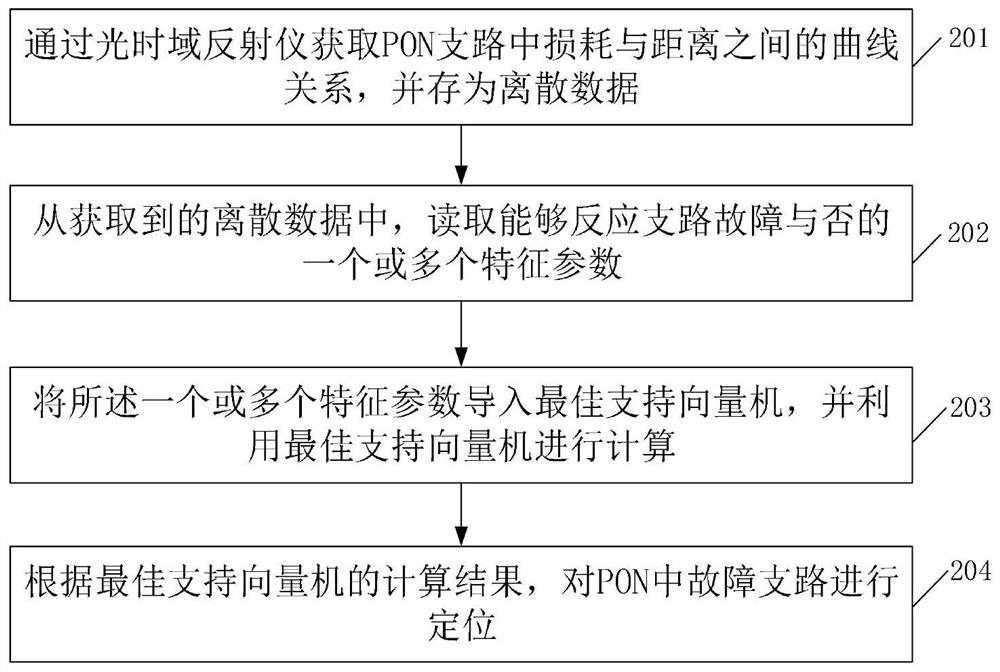
[0045] The embodiment of the present invention provides a method for locating a faulty branch in a passive optical network, which can effectively locate a faulty branch in a PON, and solve the problem that two or more branches with the same length cannot be located in a PON system problem. refer to figure 1 , after the PON completes the network deployment and starts operation, the location method of the faulty branch in the PON can be briefly summarized into four parts: acquiring data, parameter extraction, using the best support vector machine to calculate and faulty branch location, that is, steps 201- Step 204.
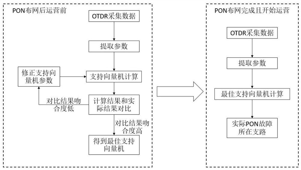
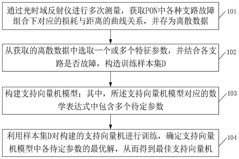
[0046] Wherein, in order to determine the optimal support vector machine, after the PON network is deployed and before the actual operation, the support vector machine needs to be trained in advance to obtain the optimal support vector machine. Therefore, the complete positioning method can be divided into two steps, first is support vector machine training after...
Embodiment 2
[0069] On the basis of the above-mentioned embodiment 1, the embodiment of the present invention also provides a faulty branch location system in a passive optical network, which can be used to implement the faulty branch location method described in embodiment 1, and solve the problem in the PON system. Two or more branches of the same length cannot be fault located.
[0070] Such as Figure 5 As shown, the faulty branch location system in the passive optical network provided by the embodiment of the present invention includes an optical time domain reflectometer OTDR, and an optical line terminal (optical line terminal, abbreviated as OLT), a circulator, and an optical splitter connected in sequence. and at least two optical network units (ONU for short), the optical time domain reflectometer is connected to the circulator. Specifically, the entire system can be divided into three parts: the central office, optical distribution network (ODN for short) and the user end. The ...
specific Embodiment approach
[0078] combine Figure 5 In the PON structure shown, it is assumed that there are four branches in the PON, and the lengths of branch 1 and branch 2 are the same. Embodiments of the present invention further provide a specific implementation of faulty branch location, including the following steps:
[0079] Step 1: Disconnect the connection between branch 1 and OUN1, use OTDR to measure the curve relationship between loss and distance, and save it as discrete data; disconnect branch 2 and OUN1, use OTDR to measure the loss and distance The curve relationship between branch 3 and OUN1 is disconnected, and the curve relationship between loss and distance is measured by OTDR, which is stored as discrete data; the connection between branch 4 and OUN1 is disconnected, and the The curve relationship between loss and distance is obtained by OTDR measurement, which is stored as discrete data; the connection between branch 1 and OUN1 is disconnected, and the connection between branch 2...
PUM
 Abstract
Description
Claims
Application Information
 - R&D
- Intellectual Property
- Life Sciences
- Materials
- Tech Scout
- Unparalleled Data Quality
- Higher Quality Content
- 60% Fewer Hallucinations
Browse by: Latest US Patents, China's latest patents, Technical Efficacy Thesaurus, Application Domain, Technology Topic, Popular Technical Reports.
© 2025 PatSnap. All rights reserved.Legal|Privacy policy|Modern Slavery Act Transparency Statement|Sitemap|About US| Contact US: help@patsnap.com


