Supercharge Your Innovation With Domain-Expert AI Agents!

Traceroute_delay diagnostic command

A technology for network path and message detection, applied in the direction of digital transmission system, electrical components, transmission system, etc., can solve the problem of not allowing to determine the delivery waiting time, end-to-end delay measurement tools not allowing operators to calculate, etc.

Inactive Publication Date: 2014-02-05
ALCATEL LUCENT SAS
View PDF5 Cites 6 Cited by
  • Summary
  • Abstract
  • Description
  • Claims
  • Application Information

AI Technical Summary

Problems solved by technology

[0015] Therefore, by returning the overall end-to-end delay in a single value that does not give any details related to its part, the latest end-to-end delay measurement tools do not allow operators to calculate which corrective actions should be applied to solve the latency budget violation ( multiple) network segments or (multiple) network nodes
[0016] Another problem with the prior art is that existing network diagnostic tools do not allow determining what portion of the overall delivery latency is due to network node dwell time

Method used


Image

  • Traceroute_delay diagnostic command
  • Traceroute_delay diagnostic command
  • Traceroute_delay diagnostic command

Examples


Embodiment Construction

[0061] A diagnostic command denoted traceroute_delay() below is provided. This name is used for naming purposes only, and is equivalent to conventional traceroute() commands (for example, RFC1393) and latency measurement issues in general. Obviously, any other name can be given.

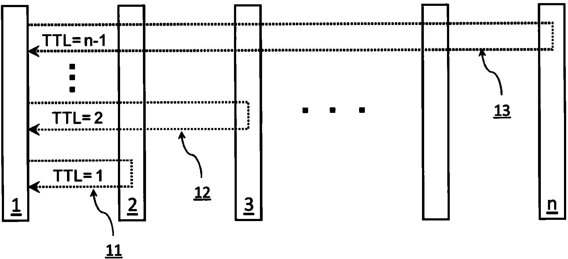
[0062] By controlling the probe message header, the traceroute_delay() command not only collects the address of the node it passes through, but also collects the residence time of the node it passes through and the propagation delay of the final link it passes through.

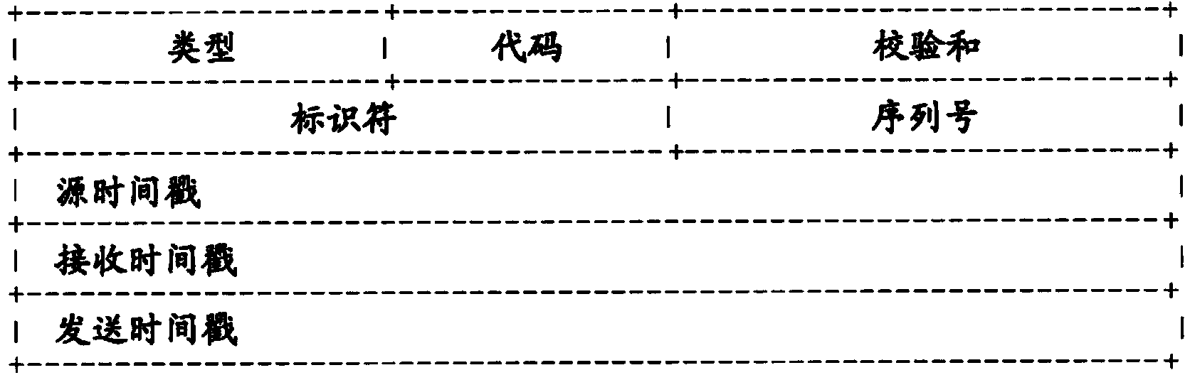
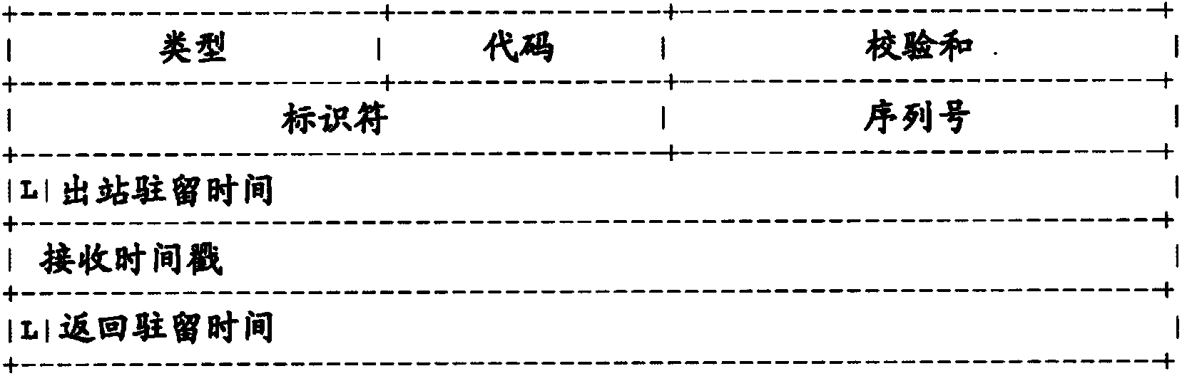
[0063] In one embodiment, the probe message is a modified ICMP message. In fact, the traceroute_delay() command makes use of ICMP timestamps, and some fields of ICMP timestamp reply messages (RFC972) differently from what is expected of them (providing new semantics to these existing fields).

[0064] refer to figure 1 and figure 2 , according to the traceroute_delay() command, the traditional ICMP timestamp and timestamp reply ...


PUM


Abstract

A method for measuring the resident time of a probe message in at least a network node comprised within a network path, said probe message provided with a Time-To-Live value, said method including the following steps: - registering the receive timestamp of the probe message; - writing the receive timestamp into a dedicated field within the received probe message; - checking the Time-To-Live value of the probe message; - if the Time-To-Live value is not null, decrementing the Time-To-Live value by one. - if the Time-To-Live value is equal to one, then: o registering the transmit timestamp of the probe message; o computing the probe message resident time within the network node by subtracting the registered receive timestamp to the registered transmit timestamp o writting the computed resident time into a field within the probe message; o changing the value of a flag within the received probe message in order to protect the resident time from being over written by subsequent action on the probe message.

Description

technical field [0001] In general, the present invention relates to the technical field of network delay / latency management. Background technique [0002] Network-induced latencies are among the most important network performance metrics because they directly affect multiple WAN applications, from real-time applications such as VoIP, interactive network games, to time-critical financial applications and location systems. [0003] Therefore, monitoring the performance of data transfer delays in a network must include a detailed understanding of how and where these delays are introduced. [0004] In traditional TDM techniques, network delays can be predicted by deterministic transition times between TDM exchanges (eg, in terms of the number of system clock transitions). However, as bandwidth requirements increased tremendously, TDM was gradually replaced by packet-switched networks (PSNs), where packet jitter, also known as packet delay variation (a stochastic process mainly ...

Claims


Application Information

Patent Timeline
Patent Type & Authority Applications(China)
IPC IPC(8): H04L12/26
CPCH04L43/0852H04L43/106H04L43/10H04L43/045H04L43/12
Inventor D·T·布伊M·勒帕莱克
Owner ALCATEL LUCENT SAS
Features
  • R&D
  • Intellectual Property
  • Life Sciences
  • Materials
  • Tech Scout
  • Unparalleled Data Quality
  • Higher Quality Content
  • 60% Fewer Hallucinations
Learn More