Supercharge Your Innovation With Domain-Expert AI Agents!

Heater configuration for melting units with non-uniform heat load

A heater and melter technology, applied in printing and other directions, can solve problems and other problems

Inactive Publication Date: 2016-06-08
XEROX CORP
View PDF5 Cites 0 Cited by
  • Summary
  • Abstract
  • Description
  • Claims
  • Application Information

AI Technical Summary

Problems solved by technology

This solution becomes problematic when the melting temperature of the ink is far from the drop temperature required for the ink to drip from the melting plate

Method used


Image

  • Heater configuration for melting units with non-uniform heat load
  • Heater configuration for melting units with non-uniform heat load
  • Heater configuration for melting units with non-uniform heat load

Examples


Embodiment Construction

[0013] see now Figure 5 , which depicts a phase change ink printer 10 . As shown, the printing press 10 includes a frame 11 to which all operating subsystems and components of the printing press 10 are mounted directly or indirectly. The printing press 10 also includes an image receiving member 12, shown in the form of a drum but which could equally be in the form of a supporting endless belt. The image receiving member 12 has an imaging surface 14 movable in a direction 16 on which a phase change ink image is formed. As used herein, "process direction" refers to the direction of movement of the image receiving member 12 as the imaging surface 14 passes the printhead to receive ejected ink, and "cross-process direction" refers to the perpendicular direction across the width of the image receiving member 12. in the direction of the processing direction. An actuator (not shown) is operatively connected to the image receiving member 12 and is configured to rotate the image re...


PUM


Abstract

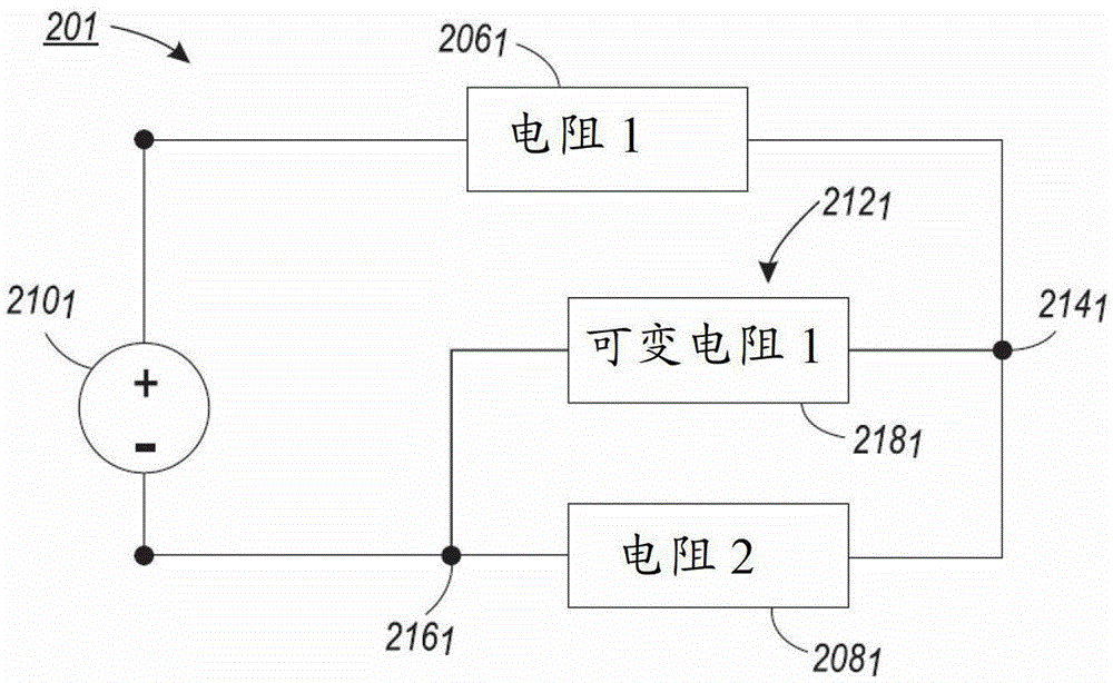
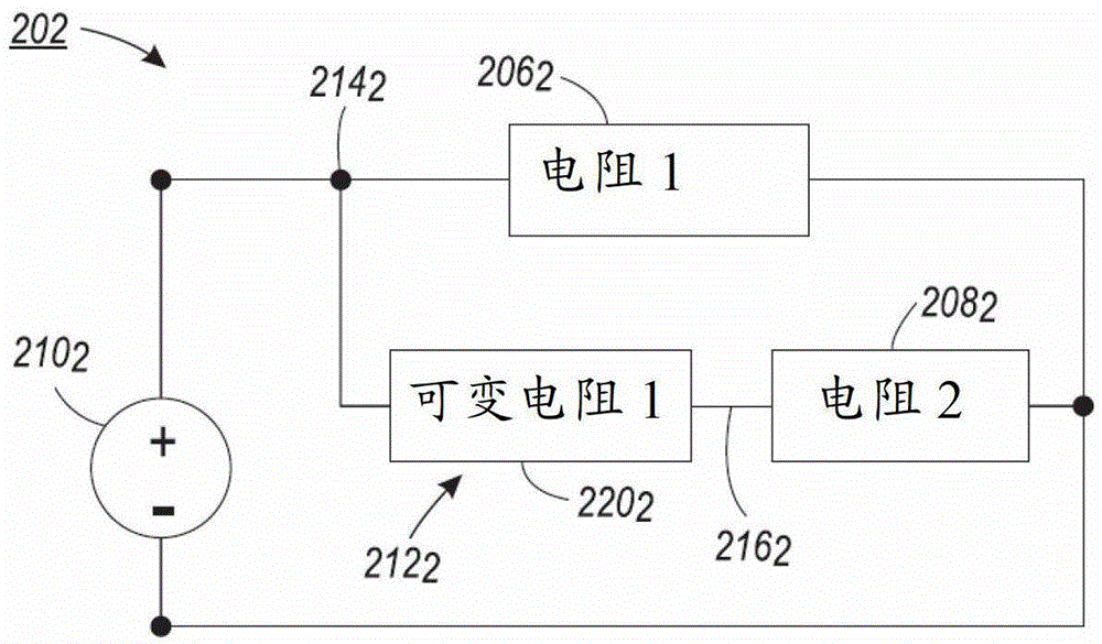
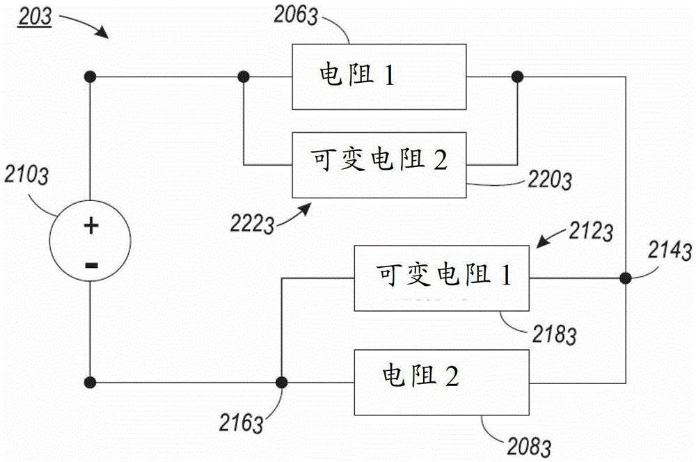
The present invention relates to a heater arrangement for a melting apparatus having a non-uniform heat load, and more particularly to a variable resistive heater element that enables current to flow through a first resistive heater element and a second resistive heater element based on its temperature. Resistive heater element. When the variable resistive heater element is below a predetermined temperature, current flows through the first resistive heater element and is restricted from flowing through the second resistive heater element. Current flows through the first and second resistive heater elements when the variable resistive heater element is at or above a predetermined temperature.

Description

technical field [0001] The present invention relates generally to heaters and, in particular, to heaters for melting phase change ink in phase change ink printers. Background technique [0002] In general, inkjet printers include at least one printhead that ejects liquid ink droplets onto the surface of an image receiving member. Phase change inkjet printers employ phase change inks that are solid at normal temperatures but transform into liquid phases at high temperatures. The molten ink can then be ejected by the printhead onto the surface of the image receiving member. The image receiving member may be a media substrate or an intermediate imaging member such as a drum or endless belt. The image on the intermediate imaging member is then transferred to an image receiving substrate. Once the ejected ink is on the image receiving surface, the ink droplets solidify rapidly to form an image. [0003] Phase change inkjet printers typically use a melting device with one or m...

Claims


Application Information

Patent Timeline
Patent Type & Authority Patents(China)
IPC IPC(8): B41J2/175
CPCB41J2/17593B41J2/17B41J2/175
Inventor 布莱恩·沃尔特·阿兹诺埃詹姆斯·B·坎贝尔
Owner XEROX CORP
Features
  • R&D
  • Intellectual Property
  • Life Sciences
  • Materials
  • Tech Scout
  • Unparalleled Data Quality
  • Higher Quality Content
  • 60% Fewer Hallucinations
Learn More