Floor air conditioner and control method thereof

A vertical air conditioner and air conditioner technology, applied in air conditioning systems, heating and ventilation control systems, heating methods, etc., can solve the problems of less hot air, affecting the comfort of air conditioning, slow heating, etc., to achieve heating and cooling Fast, integrated appearance, and improved comfort

Inactive Publication Date: 2014-02-12
GREE ELECTRIC APPLIANCES INC
View PDF9 Cites 27 Cited by
  • Summary
  • Abstract
  • Description
  • Claims
  • Application Information

AI Technical Summary

Problems solved by technology

However, the air outlets of the indoor units of the existing vertical air conditioners are all arranged on the top of the housing parts. When cooling, the air is heavier and tends to move downwards, resulting in less cold air in the upper part of the room, slow cooling and poor heating. When the temperature is high, because the air moves upwards easily, there will be less hot air in the lower part of the room, and the heating will be slow, which will affect the comfort of the air conditioner.

Method used


Image

  • Floor air conditioner and control method thereof
  • Floor air conditioner and control method thereof
  • Floor air conditioner and control method thereof

Examples


Embodiment 1

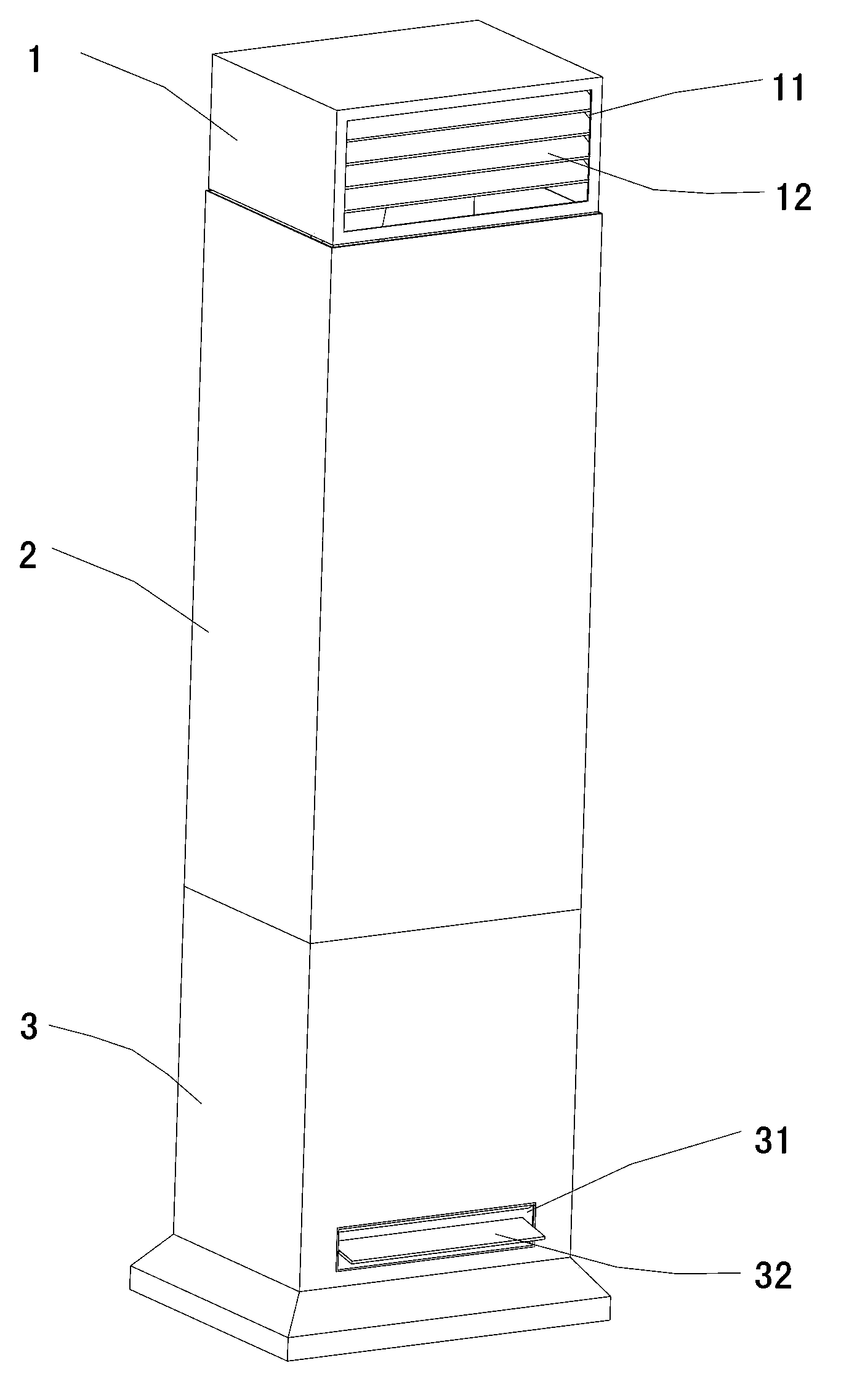
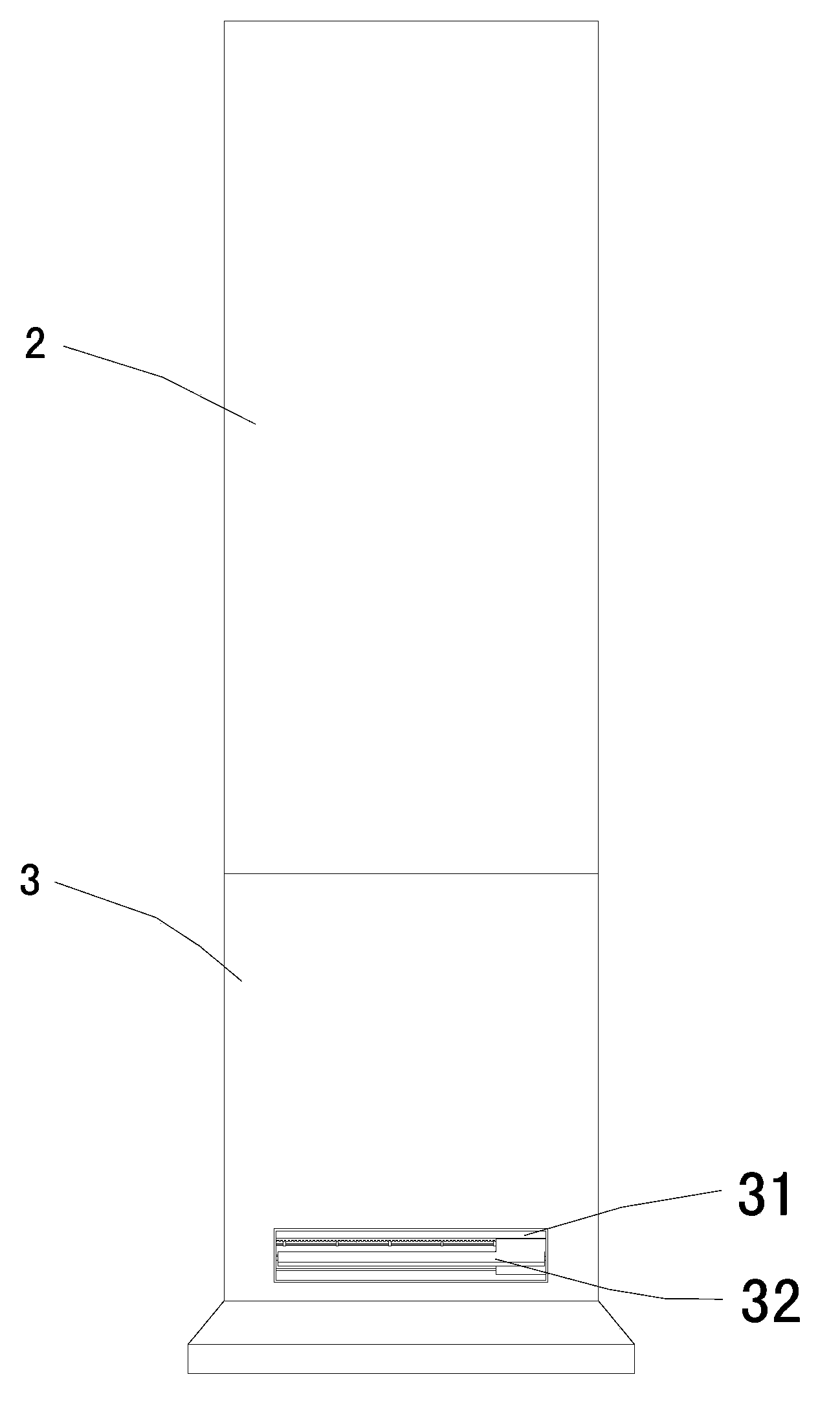
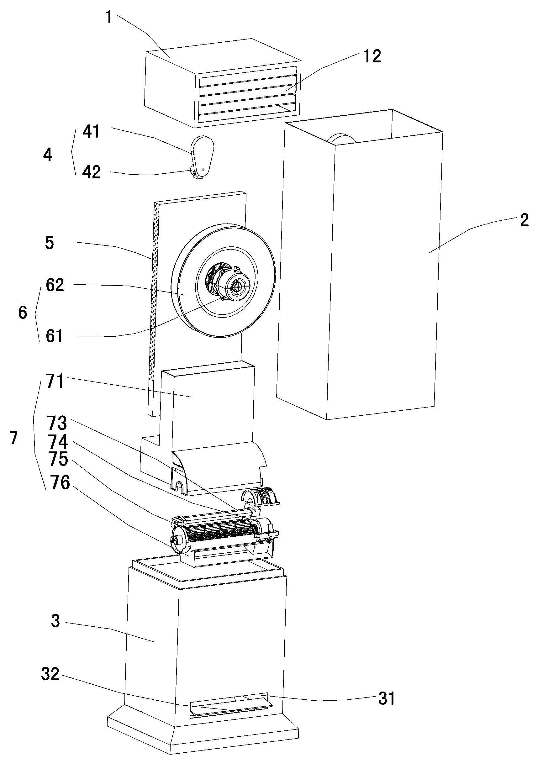
[0033] Such as Figure 1 to Figure 3 As shown, the indoor unit of the vertical air conditioner in this embodiment includes a base part 3, a housing part 2, a heat exchanger 5, a first fan 6, a first air outlet part 1, a second air outlet part 7 and a lift Mechanism 4, wherein, in addition to supporting, connecting and draining, and placing electric controls, the base part 3 is also provided with a second air outlet 31 and a second air deflector 32 on the base part 3 to realize the downward air outlet function. The cross-section of the shell part 2 is rectangular or other shapes, and the back of the shell part 2 is designed with a grille-type first air inlet 21 to realize the air intake function. A protruding opening is provided at the top of the housing part 2 . The heat exchanger 5 covers the first air inlet 21 of the housing part 2 . The heat exchanger 5 is designed in a U-shaped arc shape in conjunction with the flow field, and can also be designed in a variety of shapes ...

Embodiment 2

[0041] Such as Figure 6 As shown, the difference between the indoor unit of the vertical air conditioner in this embodiment and the first embodiment is that the first fan 6 includes a first drive motor 61, a first fan blade 62 and a third air outlet component 63, the The third air outlet component 63 includes a hollow annular air outlet body 63a and a base 63b. The inner peripheral wall of the air outlet body 63a is provided with an exhaust port communicating with its inner cavity. The first fan blade 62 is a mixed-flow air outlet. The first blade 62 is partly or completely housed in the base 63b. Preferably, the central axis of the air outlet body 63 a is parallel to the central axis of the housing part 2 . By using the mixed-flow blades and the third air outlet component 63 to cooperate, the blown air volume is increased by more than ten times, thereby increasing the heat exchange efficiency.


PUM


Abstract

The invention discloses a floor air conditioner and a control method thereof. An indoor unit of the air conditioner comprises a base component, a shell component, a heat exchanger, a first fan, a first air outlet component, a second air outlet component and a lifting mechanism, wherein the shell component is supported on the base component; the heat exchanger and the first fan are arranged in the shell component; the top of the shell component is provided with a stretching port; the first air outlet component is arranged in the stretching port in a liftable manner and provided with a first air outlet; the lifting mechanism is used for enabling the first air outlet component to perform a lifting motion so as to selectively expose or hide the first air outlet; the base component is provided with a second air outlet; the second air outlet component is arranged in the base component. The floor air conditioner provided by the invention realizes rapid heating and rapid refrigeration, and the using comfortableness of the air conditioner is improved; in addition, the first air outlet component is hidden in the shell component when not being used, so that the appearance integration is achieved, and the appearance is more attractive.

Description

technical field [0001] The invention relates to an air conditioner, in particular to a vertical air conditioner and a control method thereof. Background technique [0002] The indoor unit of the existing vertical air conditioner includes a base part, a shell part, a heat exchanger and a fan. The shell part is installed on the base part, and an air inlet and an air outlet are arranged on the shell part. At the air inlet of the casing part, the fan includes fan blades and a motor, and the fan blades are located between the heat exchanger and the air outlet. However, the air outlets of the indoor units of the existing vertical air conditioners are all arranged on the top of the housing parts. When cooling, the air is heavier and tends to move downwards, resulting in less cold air in the upper part of the room, slow cooling and poor heating. At this time, because the air is easier to move upward, there is less hot air in the lower part of the room, and the heating is slow, whic...

Claims


Application Information

Patent Timeline
Patent Type & Authority Applications(China)
IPC IPC(8): F24F1/00F24F11/00
Inventor 陈国豪孟宪运丘晓宏张玉忠
Owner GREE ELECTRIC APPLIANCES INC
Why Eureka
Try Eureka