Rocking Mass Enhanced Piezoelectric Bulk Acoustic Solid Wave Disc Microgyroscope

A piezoelectric bulk acoustic wave and mass enhancement technology, which is applied in the direction of speed measurement by gyro effect, gyroscope/steering induction equipment, and measurement device, can solve the problem that the detection electrode cannot distinguish and detect components, which is not conducive to driving, detection, and work. Problems such as modal deviation from expectations, etc., to achieve the effects of wide application range, reduced temperature sensitivity, and high Q value

Active Publication Date: 2016-03-02
SHANGHAI JIAOTONG UNIV
View PDF5 Cites 0 Cited by
  • Summary
  • Abstract
  • Description
  • Claims
  • Application Information

AI Technical Summary

Problems solved by technology

[0005] This technology has the following disadvantages: the micro-gyroscope with a rocking mass body has extremely high requirements on processing symmetry, once there is a little error, the working mode will deviate greatly from the expected; the vibration of the driving mode and the detection mode is always along the direction with the largest stiffness Therefore, the vibration antinodes of these two modes are not at the sides of the square, but at the four corners, which is very unfavorable for driving and detection; in addition, this dual-axis detection method is very unfavorable for decoupling, once the two modes Angular velocities in two directions are coupled together. Since the antinodes of the modal vibration are in the square corners, the detection electrodes cannot distinguish and detect the components in each direction; in addition, the gyroscope is too large, which limits its use in many small volumes. conditional application

Method used


Image

  • Rocking Mass Enhanced Piezoelectric Bulk Acoustic Solid Wave Disc Microgyroscope
  • Rocking Mass Enhanced Piezoelectric Bulk Acoustic Solid Wave Disc Microgyroscope
  • Rocking Mass Enhanced Piezoelectric Bulk Acoustic Solid Wave Disc Microgyroscope

Examples


Embodiment Construction

[0027] The present invention will be described in detail below in conjunction with specific embodiments. The following examples will help those skilled in the art to further understand the present invention, but do not limit the present invention in any form. It should be noted that those skilled in the art can make several modifications and improvements without departing from the concept of the present invention. These all belong to the protection scope of the present invention.

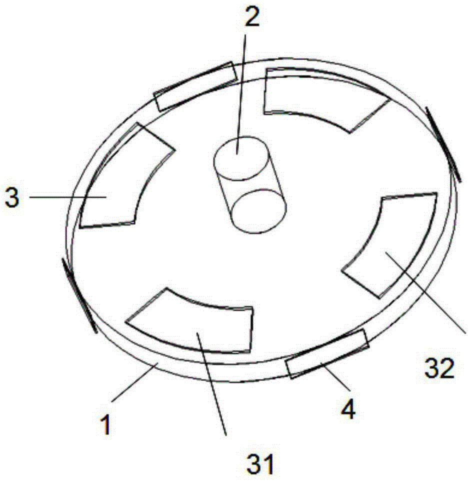
[0028] Such as figure 1 As shown, this embodiment includes:

[0029] a piezoelectric disk 1;

[0030] A rocking mass body 2, the rocking mass body 2 is fixed at the center of the piezoelectric disk 1;

[0031] Four electrodes 3 evenly distributed around the disk, the four electrodes 3 include two drive electrodes 31 and two detection electrodes 32, and the drive electrodes 31 and the detection electrodes 32 are placed at intervals;

[0032] A fixed clamping device 4, which fixes the piezoelectr...


PUM


Abstract

The invention discloses a swing quality enhanced piezoelectric acoustic solid fluctuation disc micro-gyroscope which comprises a piezoelectric disc, a swing quality body, four electrodes and a fixed clamping device, wherein the electrodes comprise two detection electrodes and two drive electrodes; the swing quality body is positioned in the center of the piezoelectric disc and is vertically fixed; the four electrodes are uniformly distributed along the periphery of the surface of the disc; the drive electrodes and the detection electrodes are arranged at intervals; the fixed clamping device is used for fixing the disc at the uniform intervals of the outer side at the periphery of the disc and is tightly clamped at the periphery of the disc. The disc structure is highly symmetrical, and a driving mode and a detection mode are just in the directions of the drive electrodes and the detection electrodes respectively. Only one pair of detection electrodes is used, and detection of angular velocity along the columnar direction of the swing quality body is promoted. The swing quality enhanced piezoelectric acoustic solid fluctuation disc micro-gyroscope is simple in structure and small in size, has the characteristics of high Q value and the like, and vacuum encapsulation is not needed.

Description

technical field [0001] The invention relates to a solid-wave gyroscope in the field of micro-electromechanical technology, specifically, it is a piezoelectric-driven piezoelectric detection disc micro-mechanical gyroscope based on the solid-wave principle. Background technique [0002] Gyroscope is an inertial device that can be sensitive to the angle or angular velocity of the carrier, and it plays a very important role in the fields of control, navigation and positioning. With the development of national defense technology and aerospace, the requirements of inertial navigation systems for gyroscopes are also developing in the direction of low cost, small size, high precision, multi-axis detection, high reliability, and adaptability to various harsh environments. The micro-gyroscope based on MEMS (Micro Electro Mechanical Systems) technology is processed by micro-nano batch manufacturing technology, and its cost, size, and power consumption are very low, and its environment...

Claims


Application Information

Patent Timeline
Patent Type & Authority Patents(China)
IPC IPC(8): G01C19/5684
CPCG01C19/5684G01C19/5698
Inventor 张卫平张弓唐健成宇翔许仲兴陈文元汪濙海
Owner SHANGHAI JIAOTONG UNIV
Why Eureka
Try Eureka