Traction pin loading device for strength test of car body
A technology of strength test and loading device, applied in the direction of railway vehicle testing, etc., can solve the problems of heavy labor, many test tools, shortened labor intensity, etc., and achieve the effect of ensuring accuracy and reliability, simple overall structure, and improving quality.
- Summary
- Abstract
- Description
- Claims
- Application Information
AI Technical Summary
Problems solved by technology
Method used
Image
Examples
Embodiment 1
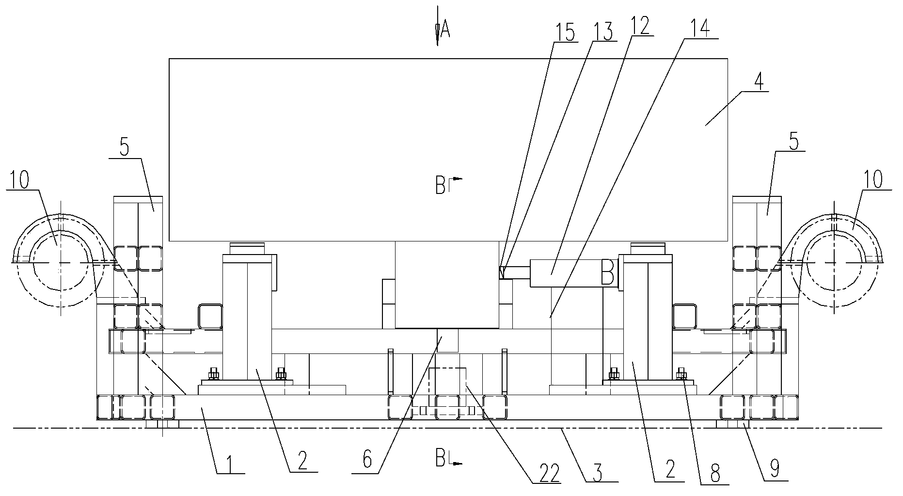
[0022] like figure 1 As shown in Fig. 1 , a loading device for the traction pin of the vehicle body strength test is a part of the strength test of the vehicle body, and is used for carrying out lateral, longitudinal and vertical loading tests on the traction pin.
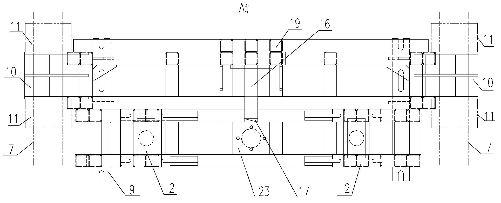
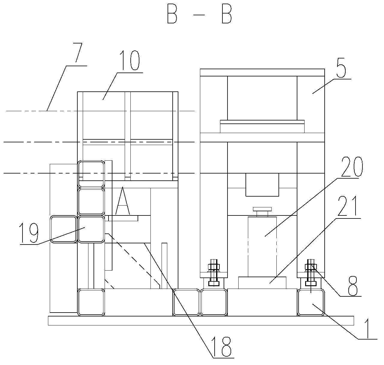
[0023] The loading device for the traction pin of the vehicle body strength test includes a base 1, a support base 2, a loading mechanism and a control unit. The loading mechanism includes a lateral loading mechanism, a longitudinal loading mechanism and a vertical Mechanism, the control unit is used to control the load applied to the traction pin by the lateral loading mechanism, the longitudinal loading mechanism and the vertical loading mechanism, and is used to collect the magnitude of the applied load and transmit or save the data.
[0024] The base 1 is fixed on the ground 3 by anchor bolts. In this embodiment, in order to improve the versatility of the device, to be applicable to different types of car bodie...
Embodiment 2
[0057] The difference from Embodiment 1 is that the first support 14 and the second support 18 adopt multi-layer backing plates, the backing plates are placed on the base 1, and the lateral loading oil cylinder 12 and the longitudinal loading oil cylinder 16 are placed on the backing plate. top. According to the required heights of the lateral loading oil cylinder 12 and the longitudinal loading oil cylinder 16, the quantity of backing plates can be arbitrarily added or subtracted. This structure is more convenient for the pick-and-place of the lateral loading oil cylinder 12 and the longitudinal loading oil cylinder 16 .
[0058] The longitudinal stop 19 in the longitudinal loading mechanism is fixed on the base 1 , the longitudinal loading cylinder 16 is placed close to the longitudinal stop 19 , and the transverse loading cylinder 12 is placed close to the support base 2 .
Embodiment 3
[0060] The difference from the above embodiment is that one lateral loading cylinder 12 and one longitudinal loading cylinder 16 are used. After the loading test in a certain direction (such as lateral direction) is completed, adjust the loading cylinder and the force sensor to the next direction (such as longitudinal) Load the test position and continue with the desired test. In this way, the cost can be saved and the operation is more flexible.
PUM
 Abstract
Description
Claims
Application Information
 - R&D
- Intellectual Property
- Life Sciences
- Materials
- Tech Scout
- Unparalleled Data Quality
- Higher Quality Content
- 60% Fewer Hallucinations
Browse by: Latest US Patents, China's latest patents, Technical Efficacy Thesaurus, Application Domain, Technology Topic, Popular Technical Reports.
© 2025 PatSnap. All rights reserved.Legal|Privacy policy|Modern Slavery Act Transparency Statement|Sitemap|About US| Contact US: help@patsnap.com


