LED single crystal cup-in-cup support

A cup-in-a-cup, single-crystal technology, applied to electrical components, circuits, semiconductor devices, etc., can solve problems such as rising product defect rate, reducing light usage rate, and prone to virtual soldering, so as to improve reflectivity and utilization rate, It is conducive to market promotion and the effect of increasing the punching area

Inactive Publication Date: 2014-02-12
东江精创注塑(深圳)有限公司
View PDF6 Cites 0 Cited by
  • Summary
  • Abstract
  • Description
  • Claims
  • Application Information

AI Technical Summary

Problems solved by technology

However, in the prior art, this kind of single crystal LED bracket has the following disadvantages. First, in order to meet the lighting requirements, sometimes two, three or four solder pads must be set at the bottom of a reflector cup at the same time. , used to install two-color and full-color LEDs. At this time, the area of ​​the pads at the bottom of the reflective cup is larger, which is larger than the area of ​​plastic filled between the pads, which makes the reflection efficiency of light lower and reduces the The utilization rate of light and the energy of the LED light source are greatly attenuated; second, the inside of the reflective cup on the LED bracket in the prior art is in a regular semi-conical shape, and it is prone to glue creeping during packaging, which brings adverse consequences. The defect rate of the product increases, and it is easy to be affected by moisture in the application; third, the pad and the solder foot are connected as a whole, which is stamped at one time during production. The solder foot of the cup is bent. At this time, the solder foot is also a whole. When bending, a large external force is required, which will affect the degree of bonding between the solder foot and the reflector cup. Moreover, the solder foot is a whole. False soldering is prone to occur during packaging, resulting in an increase in product defect rate

Method used


Image

  • LED single crystal cup-in-cup support
  • LED single crystal cup-in-cup support
  • LED single crystal cup-in-cup support

Examples


Embodiment Construction

[0017] The present invention will be further described below in conjunction with the accompanying drawings and embodiments.

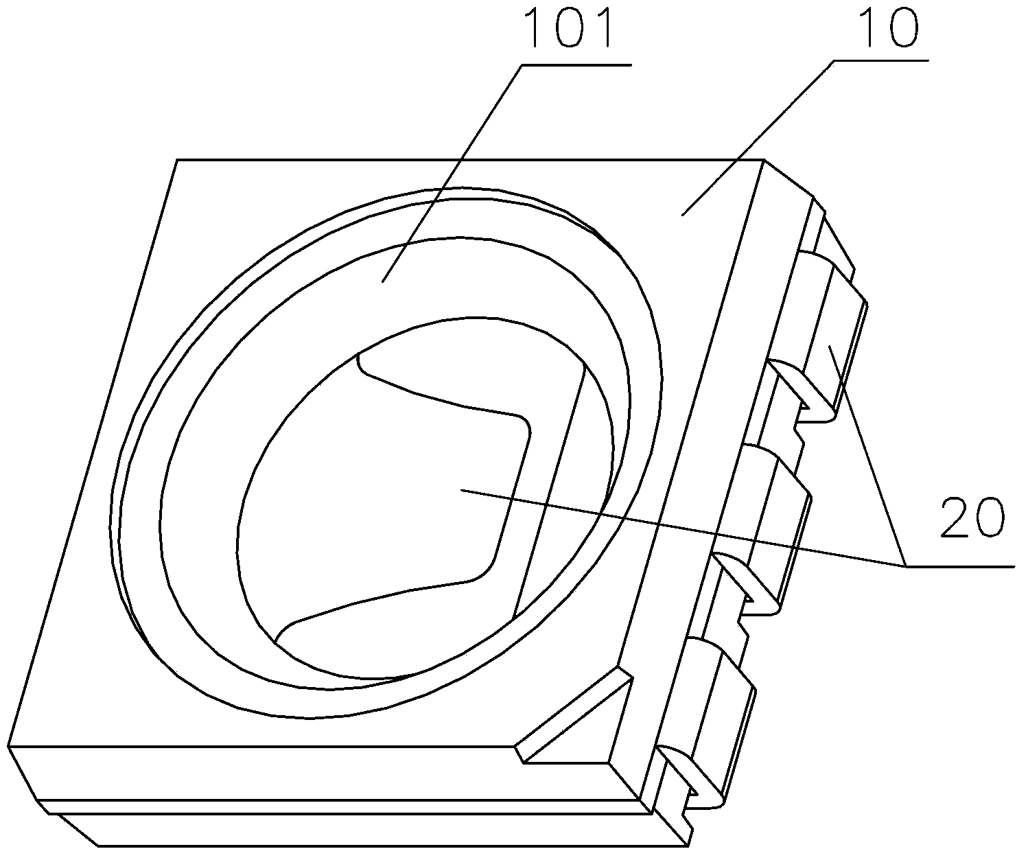
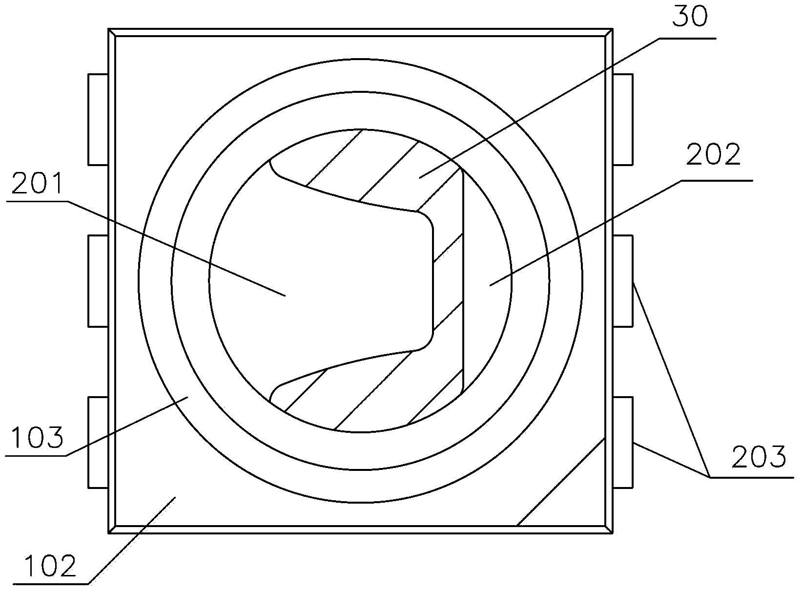
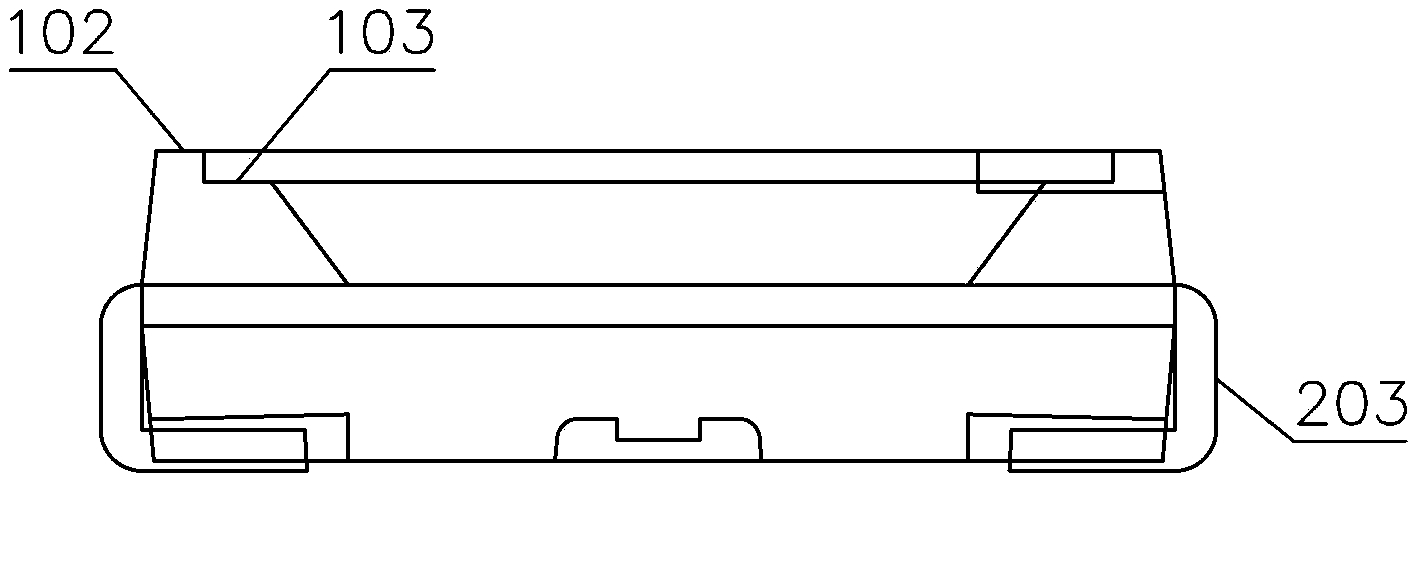
[0018] refer to figure 1 , figure 2 As shown, it is a specific embodiment of a cup holder in an LED single crystal cup disclosed by the present invention. It includes a plastic package 10 and a metal stamping part 20. A groove is formed on the upper surface of the plastic package 10 to form a reflective cup 101. The metal One end of the stamping part 20 is embedded in the plastic package 10. In this embodiment, two metal stamping parts 20 are symmetrically arranged on both sides of the plastic package 10, and one end of the two metal stamping parts 20 embedded in the plastic package 10 is respectively formed. The first pad 201 and the second pad 202 are filled with plastic 30 between the first pad 201 and the second pad 202. The first pad 201 is used to place the LED chip, and the LED chip and the second pad are connected by a gold wire. The two pads...


PUM


Abstract

The invention discloses an LED single crystal cup-in-cup support, and relates to the technical field of LED packaging. The LED single crystal cup-in-cup support comprises a plastic package body and metal punching pieces, a groove is formed in the upper surface of the plastic package body and a reflecting ring is formed, one end of each metal punching piece is arranged at the bottom of the reflecting ring and is protruded out of the bottom face of the reflecting ring to form a welding disc, the other end of each metal punching piece stretches out of the plastic package body, the top end of the reflecting ring and the bottom end of the reflecting ring are respectively in a circular shape, and the reflecting ring is in smooth transition from the top end to the bottom end. The top end of the reflecting ring is of a step structure and is composed of a first step face and a second step face, the first step face is the upper surface of the plastic package body, and the second step face is arranged in the reflecting cup and is parallel to the first step face. The LED single crystal cup-in-cup support has the advantages that due to the fact that the top end of the reflecting cup is of the step structure, the LED single crystal cup-in-cup support is not prone to being affected with damp when in use, and the plastic-climbing phenomenon does not occur during packaging. In addition, the LED single crystal cup-in-cup support increases the plastic filling area between the two welding discs, enables the plastic area of the bottom of the reflecting cup during injection molding to be increased, and improves the reflection rate and the using rate of light.

Description

【Technical field】 [0001] The present invention relates to the field of LED technology, and more specifically, the present invention relates to a cup-in-cup holder for an LED single crystal cup. 【Background technique】 [0002] With the development of LED lighting technology, LED is more and more widely used in people's daily life. The existing single crystal LED brackets all include a reflector and two pads fixedly installed at the bottom of the reflector. On the other hand, when in use, an LED chip is placed on the first pad, and then connected to the other pad through a gold wire. The pad is generally connected to an external solder pin, and then the packaging process is completed by encapsulation potting. However, in the prior art, this kind of single crystal LED bracket has the following disadvantages. First, in order to meet the lighting requirements, sometimes two, three or four solder pads must be set at the bottom of a reflector cup at the same time. , used to insta...

Claims


Application Information

Patent Timeline
Patent Type & Authority Applications(China)
IPC IPC(8): H01L33/48H01L33/60H01L33/62
CPCH01L33/483H01L33/60H01L33/62
Inventor 刘水东陈琨张建兴
Owner 东江精创注塑(深圳)有限公司
Why Eureka
Try Eureka