Hidden access door with metal rotating shafts

A technology for hardware shafts and inspection doors, which is applied to door leaves, windows/doors, door/window accessories, etc. It can solve problems such as damage to the corners of the inspection door trim panels, inability to disassemble, and difficulty in smooth docking, etc., to increase the maintenance space, The effect of avoiding material waste and improving aesthetics

Active Publication Date: 2014-02-19
GOLD MANTIS CONSTR DECORATION
View PDF12 Cites 6 Cited by
  • Summary
  • Abstract
  • Description
  • Claims
  • Application Information

AI Technical Summary

Problems solved by technology

This approach brings some disadvantages during maintenance: 1. When the maintenance door is opened, a part of the space in the maintenance hole will be occupied by the maintenance door, and the actual usable space is greatly reduced; 2. When the maintenance door is opened at a large angle, the maintenance door and the door The materials are easy to collide, which will cause damage to the corners of the inspection door trim panel; 3. The corners of the inspection door need to be chamfered, which will easily lead to the edge of the trim panel (such as stone veneer), black seams are easy to appear around the inspection door, and the aesthetics are not enough; 4. The texture of the decorative material of the inspection door and the surrounding texture are difficult to connect smoothly (such as stone veneer); 5. If the inspection door is damaged, it cannot be disassembled

Method used


Image

  • Hidden access door with metal rotating shafts
  • Hidden access door with metal rotating shafts
  • Hidden access door with metal rotating shafts

Examples


Embodiment

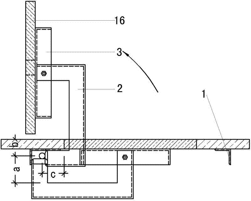
[0026] Example: such as figure 1 As shown, a hidden hardware rotating shaft inspection door includes an outer ring 1 , a moment arm 2 and an inner ring 3 .

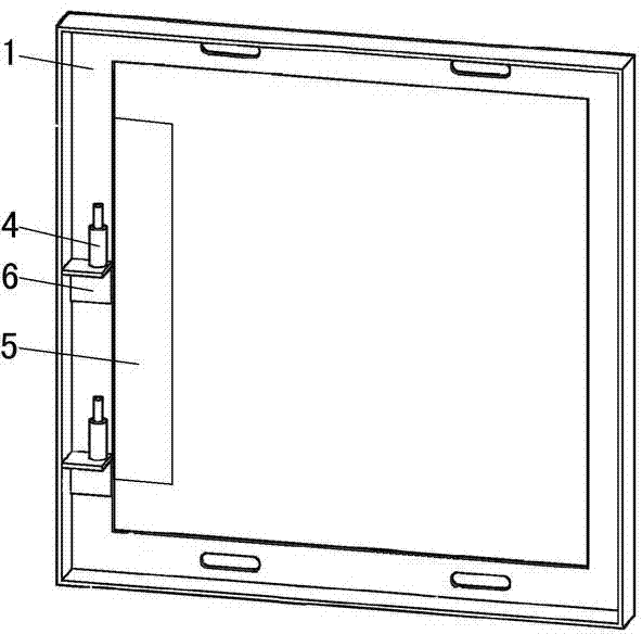
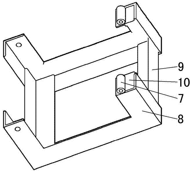
[0027] like figure 2 , Figure 5 , Image 6 , Figure 7 Shown, outer ring 1 is made up of angle steel ring, oblong hole, rotating shaft 4, angle steel 2 6, limit flat iron 5. The outer ring 1 is an angle steel ring welded by angle steel, one side is welded with a shaft 4, and the shaft 4 is arranged inside the angle steel ring, and the upper and lower sides are provided with oblong holes, and the outer ring 1 is welded with an angle steel 6, through which the shaft 4 is fixed. Angle steel two 6 fix the rotating shaft 4, keep the central axis of the rotating shaft 4 and the central axis of the rotating shaft accessories 7 in the same straight line, and perpendicular to the ground. The outer ring 1 is provided with a limit flat iron 5 on one side of the welding shaft 4, and the thickness of the limit flat iron 5 is co...


PUM


Abstract

The invention discloses a hidden access door with metal rotating shafts. The hidden access door comprises an outer ring (1), an actuating arm (2) and an inner ring (3). The rotating shafts (4) are welded on one side of the outer ring (1), oblong holes are formed in the upper edge and the lower edge of the outer ring (1), and the outer ring (1) is fixed on the reverse side of a decorative face (14) through the oblong holes and a back bolt (15). The actuating arm (2) is stool-shaped and comprises four foot stands, rotating shaft accessories (7) are arranged at two adjacent foot stand ends of the actuating arm (2), and round holes are formed at another foot stand ends of the actuating arm (2). The actuating arm (2) penetrates the outer ring (1) to be connected with the rotating shafts (4). Round holes are formed in the upper top face and the lower top face of the inner ring (3), and oblong holes are formed in the left side and the right side of the inner ring (3). The inner ring (3) is connected with the round holes of the actuating arm (2), and is connected with a veneer (16) to form an integral structure. Through the action of turning the actuating arm, maintenance space is enlarged; collision between the access door and materials around the door is avoided; beveling of edges and corners of the access door is not needed, and accordingly, attractiveness in appearance is improved; the access door is convenient to demount.

Description

technical field [0001] The invention relates to an inspection door with a hidden hardware rotating shaft. Background technique [0002] The traditional method of concealing the inspection door is usually to use the sky and earth shaft, and directly fix the shaft at the upper and lower ends of the door, similar to the method of the floor spring door. This approach brings some disadvantages during maintenance: 1. When the maintenance door is opened, a part of the space in the maintenance hole will be occupied by the maintenance door, and the actual usable space is greatly reduced; 2. When the maintenance door is opened at a large angle, the maintenance door and the door The materials are easy to collide, which will cause damage to the corners of the inspection door trim panel; 3. The corners of the inspection door need to be chamfered, which will easily lead to the edge of the trim panel (such as stone veneer), black seams are easy to appear around the inspection door, and the...

Claims


Application Information

Patent Timeline
Patent Type & Authority Applications(China)
IPC IPC(8): E06B5/00E06B3/70E05D3/06
Inventor 米央孙凤标金夏晴吴贞义孙春雷王国绪吴贤许立江卢野姚连月徐亮曹建元魏海尘汤海波徐建云曾根元
Owner GOLD MANTIS CONSTR DECORATION
Why Eureka
Try Eureka