
Total station tripod antiskid locking device

A technology for locking devices and tripods, which is applied in the direction of machines/brackets, supporting machines, mechanical equipment, etc., can solve the problems of easy sliding of total station tripods, and achieve the effects of avoiding micro-slipping of instruments, saving working time, and improving safety

Inactive Publication Date: 2014-02-19
LIUZHOU RAILWAY VOCATIONAL TECHN COLLEGE
View PDF4 Cites 8 Cited by
  • Summary
  • Abstract
  • Description
  • Claims
  • Application Information

AI Technical Summary

Problems solved by technology

[0005] The technical problem to be solved by the present invention is to provide a tripod anti-slip locking device for a total station that can effectively play an anti-slip effect, effectively improve the measurement efficiency, quality and precision of the total station, and solve the problem of the above-mentioned prior art. The problem that the total station tripod is easy to slide in

Method used


Image

  • Total station tripod antiskid locking device
  • Total station tripod antiskid locking device
  • Total station tripod antiskid locking device

Examples


Embodiment 1

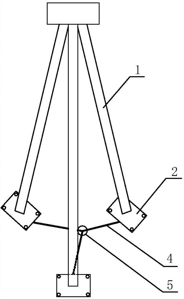
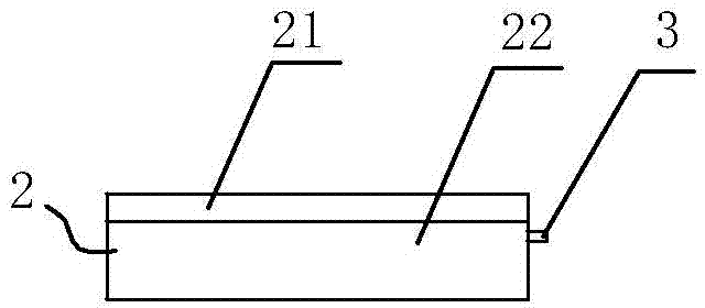
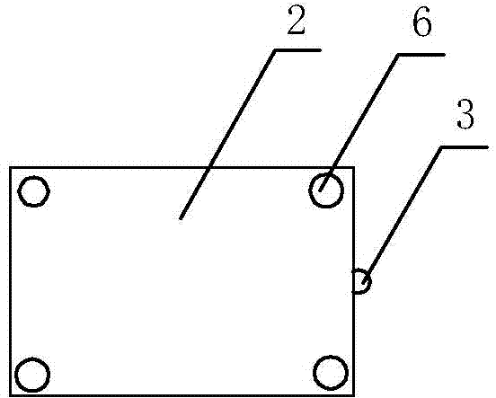
[0024] Example 1: An anti-skid locking device for the tripod of a total station, such as figure 1 As shown, the tripod 1 is included. The tip of the tripod foot is provided with a non-slip foot pad 2. The non-slip foot pad is mainly composed of an upper locking layer 21 and a lower friction layer 22. The bottom surface of the lower friction layer is provided with anti-skid patterns, and the bottom of the lower friction layer The solid layer and the lower friction layer are connected by pins 6 (see Figure 2-Figure 3 ). The upper locking layer of the anti-slip foot pad mainly allows the tip of the tripod to be inserted into it to lock, and the lower friction layer mainly ensures that the foot pad does not slide through the friction between the bottom surface and the ground to achieve the anti-skid effect of the total station tripod. The said non-slip foot pads are set as three separate small non-slip foot pads. The plane size of each small non-slip foot pad is 100×100mm, the uppe...

Embodiment 2

[0027] Embodiment 2: An anti-skid locking device for a total station tripod, comprising a tripod 1, the tip of the tripod foot is provided with an anti-skid foot pad 2, and the anti-skid foot pad is mainly composed of an upper locking layer 21 and a lower friction layer 22 , The bottom surface of the lower friction layer is provided with anti-slip patterns, the upper locking layer and the lower friction layer are connected by pins 6. The anti-slip foot pad is set as a large anti-slip foot pad with an integral structure, and the three toes of the tripod are all installed on the big anti-slip foot Mat (such as Figure 5 Shown). The stability of this structure is greater; but it has high requirements for the flatness of the ground (affecting the leveling operation and accuracy of the instrument), and also affects the activities of the test personnel (affecting standing, easy to touch). This structure does not require additional foot and leg locking and stopping structures.

[0028...


PUM


Abstract

The invention relates to a total station tripod antiskid locking device which comprises a tripod. The tip ends of legs of the tripod are provided with antiskid leg mats. Each antiskid leg mat is mainly formed by an upper locking layer and a lower frictional layer. The antiskid leg mats are three small separated antiskid leg mats which are correspondingly arranged on the three tip ends of the legs of the tripod, or the antiskid leg mats are a large integral antiskid leg mat on which the three leg tip ends of the tripod are all arranged. When the small separated antiskid leg mats are adopted, a leg mat locking structure or a leg locking structure is further arranged. When a total station is used in a place where the ground or the road surface is smooth, the total station tripod antiskid locking device can play a role in skid resistance, so that the measuring efficiency, the measuring quality, the measuring precision, the measuring safety and the like of the total station are effectively improved, and especially on a rainy day, the antiskid effect is more obvious.

Description

Technical field [0001] The invention relates to an anti-skid locking device for a tripod of a total station. Background technique [0002] At present, the tripod legs of the total station are made of wood and metal. The tips of the feet are all metal cone-shaped structures. It is easy to press the toes into the ground when working in the field, so that the total station can stand firmly and facilitate the measurement. [0003] But when the work site is road concrete pavement, square brick ground, classroom polished brick ground, because the toe of the total station tripod touches the semi-smooth, smooth ground, the open tripod is difficult to stand firmly. The toe does not slide when the tripod has a small opening and the stand tends to be vertical, but the tripod is easy to overturn and lose stability; when the tripod has a large opening, the toes are easy to slide and cause sliding instability. [0004] The reason for this problem is that the toe part of the existing tripod has a ...

Claims


Application Information

Patent Timeline
Patent Type & Authority Applications(China)
IPC IPC(8): F16M11/38
Inventor 梁斌何江斌罗斯琪郭程方杨波潘家诚
Owner LIUZHOU RAILWAY VOCATIONAL TECHN COLLEGE
Learn More