
Image positioning method of banknote printing plate

An image positioning and image technology, applied in the direction of instruments, character and pattern recognition, computer parts, etc., can solve the problems of poor accuracy, slow speed, low efficiency and so on

Active Publication Date: 2014-02-19
BEIJING BANKNOTE CURRENCY DESIGNING & PLATING +2
View PDF4 Cites 14 Cited by
  • Summary
  • Abstract
  • Description
  • Claims
  • Application Information

AI Technical Summary

Problems solved by technology

[0004] For this reason, the technical problem to be solved by the present invention is that the method for setting the positioning kernel on the template image in the prior art is slow, inefficient, and poor in accuracy, and a banknote with high speed, high efficiency, and high accuracy is provided Image positioning method of printing plate

Method used


Image

  • Image positioning method of banknote printing plate
  • Image positioning method of banknote printing plate
  • Image positioning method of banknote printing plate

Examples


Embodiment Construction

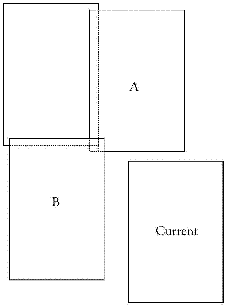
[0047] The image positioning method of the banknote printing plate provided by the present invention is used for the detection of the sample banknote printing plate. The sample banknote printing plate first needs to be photographed, and the camera takes pictures of the sample banknote printing plate at a fixed distance After the computer collects the images to be detected in consecutive frames, the positioning method provided by the present invention is used to realize the positioning of the images to be detected and the template image, and then image detection is performed.

[0048]The image positioning method of banknote printing plate provided by the present invention comprises the following steps:

[0049] 1. Establish a positioning template: select a group of complete template images, and set a positioning kernel on each frame of the template image in turn to form the positioning template. The complete template image is obtained by two-dimensional scanning; the positioning...


PUM


Abstract

The invention relates to an image positioning method of a banknote printing plate. The image positioning method comprises the steps of positioning template establishment, image splicing and image positioning. The steps are carried out in a circulation mode until all frame images of an image to be detected and an image of the positioning template are positioned. The image positioning method solves a problem that an acquired image cannot be precisely positioned relative to the template image because of image translation, rotation, scaling and the like caused by uncertain factors such as mechanical error, printing plate deformation and the like in the process of two-dimensional scanning and shooting of a camera through an image precise positioning algorithm with multiple positioning cores, and has the advantages of high positioning speed, high efficiency and high accuracy.

Description

technical field [0001] The invention belongs to the technical field of printing plate quality inspection instruments, in particular to an image positioning method for banknote printing plates. Background technique [0002] After the banknote printing plate is manufactured, it is necessary to use the printing plate quality inspection device to check the quality of the printing plate. During the inspection, first fix the printing plate on the workbench, and then drive the camera to move, so that the camera performs a two-dimensional scanning movement relative to the workbench along the X and Y axes; during the movement, the camera scans the printing plate at a fixed distance. After the computer collects the images to be detected in consecutive frames, the template image is positioned with the image to be detected, and then the positioning template image after positioning is compared with the high and low threshold templates corresponding to the collected images to be detected ...

Claims


Application Information

Patent Timeline
IPC IPC(8): G06K9/32G06K9/60
Inventor 刘永江杜旭东毕明张健贾可付茂栗孙晓刚张建龙成王雪
Owner BEIJING BANKNOTE CURRENCY DESIGNING & PLATING
Learn More