
A Butler matrix structure

A technology of Butler matrix and directional coupler, applied in the field of Butler matrix structure, can solve the problems of rising insertion loss, complex overall structure of Butler matrix, and increasing number of cross points, etc., so as to reduce insertion loss, reduce the number and distribute reasonable effect

Active Publication Date: 2015-11-18
ZTE INTELLIGENT IOT TECH
View PDF6 Cites 0 Cited by
  • Summary
  • Abstract
  • Description
  • Claims
  • Application Information

AI Technical Summary

Problems solved by technology

At present, the directional couplers and phase shifters used in the traditional Butler matrix structure both use a 1 / 4 wavelength transmission line structure, so they can only work in a single frequency band
[0004] With the continuous expansion of the application platform, the number of ports in the Butler matrix is ​​also increasing, the overall structure of the Butler matrix is ​​becoming more and more complex, the number of intersections is also increasing significantly, and the resulting insertion loss is also increasing.

Method used


Image

  • A Butler matrix structure
  • A Butler matrix structure
  • A Butler matrix structure

Examples


Embodiment Construction

[0028] The following will clearly and completely describe the technical solutions in the embodiments of the present invention with reference to the accompanying drawings in the embodiments of the present invention. Obviously, the described embodiments are only some of the embodiments of the present invention, not all of them. Based on the embodiments of the present invention, all other embodiments obtained by persons of ordinary skill in the art without creative efforts fall within the protection scope of the present invention.

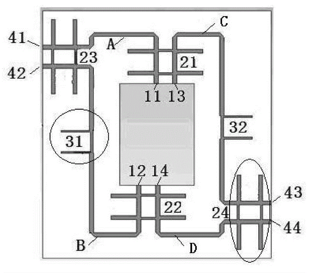
[0029] The basic structure of the Butler matrix structure provided by an embodiment of the present invention includes a plurality of input ports, a plurality of output ports, a plurality of directional couplers and a plurality of phase shifters. Wherein, the plurality of input ports and the plurality of output ports are connected to each other through a network composed of the plurality of directional couplers and the plurality of phase shifters, and e...


PUM


Abstract

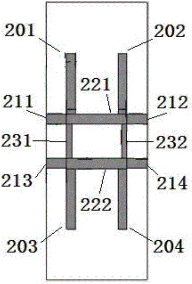
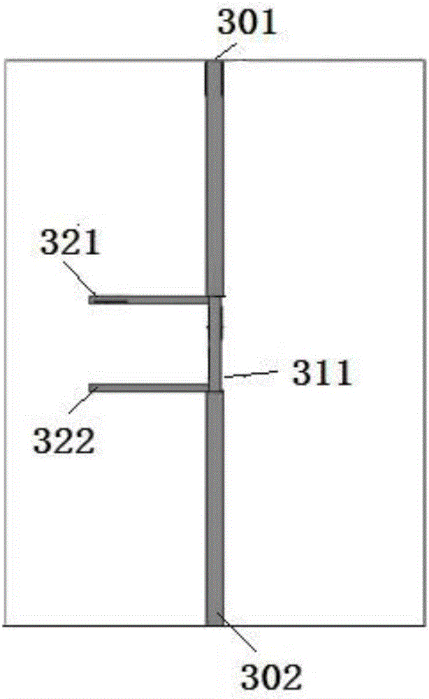
An embodiment of the invention provides a butler matrix structure which can work at a dual-band, is simplified in structure, can reduce insertion loss and improves transmission efficiency. The butler matrix structure comprises a plurality of input ports, a plurality of output ports, a plurality of directional couplers and a plurality of phase shifters. The input ports are connected with the output ports through a network composed of the directional couplers and the phase shifters . Each output port is connected with an antenna array unit. Meanwhile, the input ports are located in the middle of the butler matrix structure. The output ports are symmetrically located on the two sides of the butler matrix. Each directional coupler is formed by enabling two pi-type structures tobe in butt joint. Each phase shifter is of a pi-type structure.

Description

technical field [0001] The invention relates to the technical field of microwave antenna engineering, in particular to a Butler matrix structure. technical background [0002] The concept of Butler matrix was first proposed in 1961. Each beam that can be formed by the Butler matrix can obtain the gain provided by the entire antenna surface, which is a multi-beam forming method without loss of gain. Since the formed multi-beams are orthogonal, it is very beneficial to the synthesis of the pattern of other complex antennas. At the same time, the formed multi-beams can be used for both transmission and reception, and can be implemented with various transmission lines, making it possible to share multi-beam receiving and transmitting antennas. In addition, compared with other multi-beam and adaptive beam-forming methods, the Butler multi-beam array forming network has a simple network structure, low cost, and is easy to achieve broadband. It has great potential as a feed netwo...

Claims


Application Information

Patent Timeline
Patent Type & Authority Patents(China)
IPC IPC(8): H01Q3/40H01Q21/00
Inventor 王金龙冯春楠傅佳辉
Owner ZTE INTELLIGENT IOT TECH
Learn More