Fixture for replacing strain insulator string

A technology of tension insulators and fixtures, which is applied in the direction of overhead lines/cable equipment, etc., and can solve problems such as insulator insulation failure and insulation impact

Inactive Publication Date: 2014-02-19
STATE GRID CORP OF CHINA +1
View PDF4 Cites 8 Cited by
  • Summary
  • Abstract
  • Description
  • Claims
  • Application Information

AI Technical Summary

Problems solved by technology

During operation, the two splints of the fixture on the cross-arm side are clamped successively on the hanging point of the hardware on the cross-arm side, and the cavity of the fixture on the wire side is fastened to the screw of the right-angle hanging plate, and then the shrinkage assembly is operated to loosen the insulator string. Then replace the degraded insulators in the loosened insulator strings. During the operation, the metal double-headed screw in the shrink assembly and the insulator string are on the same plane, and they are located on both sides of the insulator string, and are electrically conductive by the metal double-headed screw. Influenced by insulators, the insulation of several insulators on the insulator string that coincides with the lead screws on both sides will be greatly affected. In the process of live replacement, it is likely to cause the insulation failure of the insulators there.

Method used


Image

  • Fixture for replacing strain insulator string
  • Fixture for replacing strain insulator string
  • Fixture for replacing strain insulator string

Examples


Embodiment 1

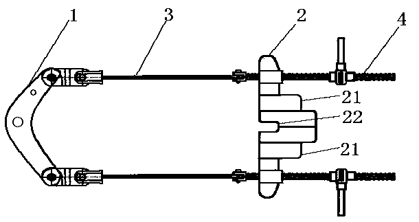
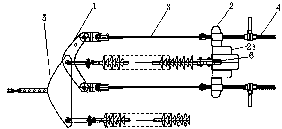
[0018] as attached figure 2 As shown, this embodiment replaces the clamps for the side strings of strain insulators, including the cross-arm side clamp 1, the conductor side clamp 2, and the insulation connection device connecting the cross-arm side clamp 1 and the conductor side clamp 2, for A tightening device for tightening the relative distance between the cross-arm side fixture 1 and the wire side fixture 2. The cross-arm side fixture 1 is an integral component, and the cavity in the middle of the cross-arm side fixture 1 and the cross-arm side fitting The two ends of the connecting plate 5 are matched, and the wire side fixture 2 is composed of two front and rear sub-fixtures 21, and the front and rear two sub-fixtures 21 are detachably connected. There is a through groove 22 extending along the length direction of the joint surface. The through groove 22 on the sub-fixture can be snapped into the three-eye fitting plate 6 for hanging the wire after the two-point fixtur...


PUM


Abstract

The invention relates to a tool for power construction, especially to a fixture for replacing a strain insulator string. The fixture comprises a cross-arm side clamp, a lead side clamp, an insulated connector and a tightening device, wherein the cross-arm side clamp is connected with the lead side clamp via the insulated connector, and the insulator connector is arranged at the two sides between the cross-arm side clamp and the lead side clamp; and the tightening device is used for shortening the relative distance between the cross-arm side clamp and the lead side clamp, is arranged at the two sides of the lead side clamp, penetrates through the lead side clamp and is then connected with the lead side clamp. The fixture of the invention can be conveniently, stably and fixedly mounted on line fittings where the strain insulator string is placed. In the process of insulator replacement, the two parallel sides of the insulator string are only equipped with insulated pull rods which are not conductive, and metal leading screws are placed behind the cross-arm side clamp and distanced from the insulator string, so that insulation performance of the insulator is not influenced.

Description

technical field [0001] The invention relates to a power working tool, in particular to a jig for replacing side strings of tension insulators. Background technique [0002] Existing equipment for replacing tension side string insulators of 500kV lines, as attached figure 1 As shown, it includes the clamp on the cross-arm side, the clamp on the wire side, and two sets of contraction assemblies whose two ends are respectively hinged to the two ends of the clamp on the cross-arm side and the clamp on the wire side. The clamp on the cross-arm side is a split type. It consists of two separate splints with symmetrical cavities. The cavity of the fixture on the cross-arm side matches the hanging point of the hardware on the cross-arm side. The shrinkage assembly is composed of a double-ended screw and an insulating tie rod. During operation, the two splints of the fixture on the cross-arm side are clamped successively on the hanging point of the hardware on the cross-arm side, and...

Claims


Application Information

Patent Timeline
Patent Type & Authority Applications(China)
IPC IPC(8): H02G1/02
Inventor 王利华饶建彬安锋黄立邱中华
Owner STATE GRID CORP OF CHINA
Why Eureka
Try Eureka