Anti-twist device

A twist-stop and roller technology, applied in the field of twist-stop devices, to achieve the effect of simple and fast replaceability

Inactive Publication Date: 2012-06-13
OERLIKON TEXTILE GMBH & CO KG
View PDF2 Cites 0 Cited by
  • Summary
  • Abstract
  • Description
  • Claims
  • Application Information

AI Technical Summary

Problems solved by technology

[0006] The anti-twist device known from US 6408608 B1 also has an anti-twist roller directly supported on one end of the shaft, which leads to the known disadvantages

Method used


Image

  • Anti-twist device
  • Anti-twist device
  • Anti-twist device

Examples


Embodiment Construction

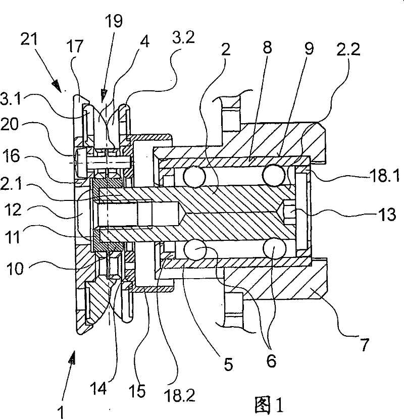
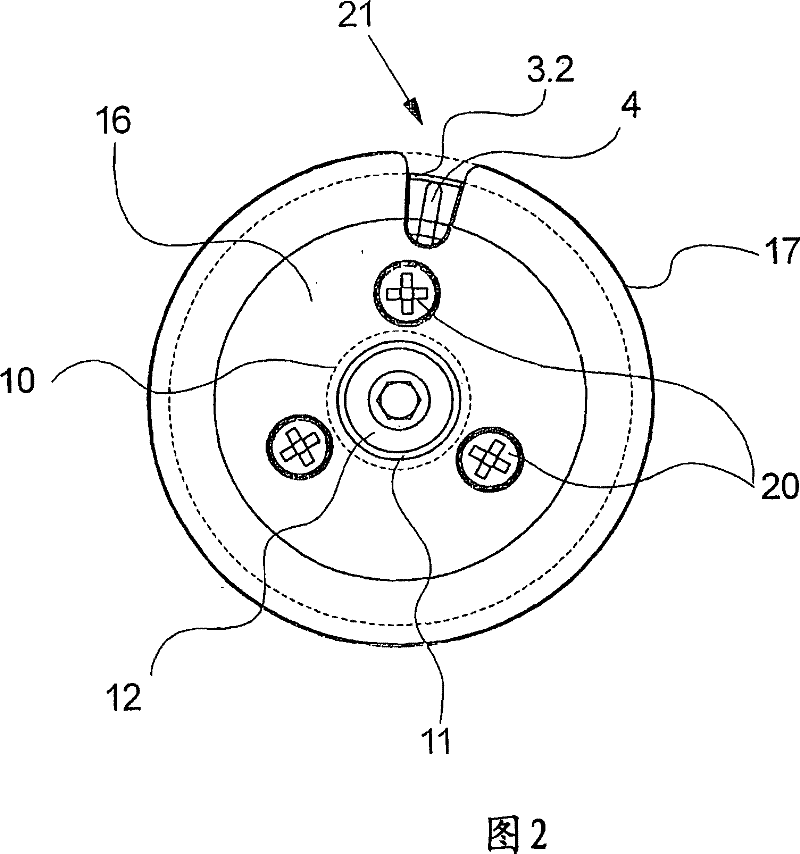
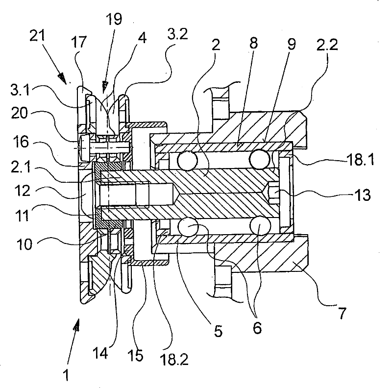
[0023] figure 1 A simplified cross-sectional view of an embodiment of the anti-twist device of the present invention is shown in FIG. figure 2 A side view of this embodiment is shown. As long as one figure is not specifically mentioned, the following description applies equally to both figures.

[0024] The anti-twist device has a shaft 2 . The shaft 2 projects with a bearing end 2.2 into a bearing sleeve 5 . A plurality of rolling bodies 6 are arranged in the bearing sleeve 5 between the circumference of the shaft 2 and the bearing sleeve 5 . The bearing sleeve 5 has a cover 18.1 and 18.2 on each of its end faces. The cover 18 . 2 is annular and extends between the inner diameter of the bearing sleeve 5 and the circumference of the shaft 2 . The shaft 2 protrudes beyond the bearing sleeve 5 with a retaining end 2.1. The anti-twist roller 1 is supported on the circumference of the shaft 2 at the retaining end 2.1. The anti-twist roller 1 has two ceramic discs 3.1 and ...


PUM


Abstract

The invention relates to an anti-twist device for guiding a thread, comprising an anti-twist roller (1) and a shaft (2) having a retaining end (2.1) with a rotationally fixed connection to the anti-twist roller and a bearing end (2.2) for bearing the shaft. The anti-twist roller is preferably configured by two ceramic disks (3.1, 3.2) with axially overlapping webs (4) for producing a zigzag threadline track (19). The aim of the invention is to provide an anti-twist roller with a long-lasting bearing while guaranteeing replaceability of the expendable parts. For this purpose, the bearing end of the shaft is rotationally received in a bearing bush (5) and said bearing bush (5) is detachably connected to a roller carrier (7) as a modular unit comprising the mounted shaft and the anti-twist roller.

Description

technical field [0001] The invention relates to an anti-twist device for guiding a thread. [0002] Background technique [0003] In the manufacture of textured yarns according to the false twist principle, it is known that false twists are generated on the threads of multifilaments by friction, which propagates in the threads opposite to the direction of thread travel, whereby the propagating twisted threads can be in a so-called Heating and setting in the false twist zone. In order to avoid the uncontrolled reverse run of the false twist in the thread, a twist stop is used which has a twist stop roller for each thread, which comprises a meander-shaped thread path formed on the circumference. [0004] Such a twist stop is known, for example, from DE 1158422. In the known anti-twist device, the anti-twist roller (Drallstoprolle) consists of two discs, which overlap each other with the ribs protruding in the axial direction, so that a zigzagging thread travels between the t...

Claims


Application Information

Patent Timeline
Patent Type & Authority Patents(China)
IPC IPC(8): B65H57/14D02G1/02
CPCD02G1/04B65H2701/31B65H57/14D02G1/02
Inventor R·菲雷尔
Owner OERLIKON TEXTILE GMBH & CO KG
Why Eureka
Try Eureka