Silk detection device

A detection device and silk thread technology, applied in other manufacturing equipment/tools, textiles and papermaking, manufacturing tools, etc., can solve the problems of inconvenient and cumbersome replacement of silk rolls, and the impact of system production efficiency

Inactive Publication Date: 2020-10-30
岳西县长宁织绸有限责任公司
View PDF0 Cites 0 Cited by
  • Summary
  • Abstract
  • Description
  • Claims
  • Application Information

AI Technical Summary

Problems solved by technology

When the above-mentioned silk rolls were placed on the silk feed rack, the silk was connected to the warp beam by the shuttle. When the silk was woven, the following two situations would occur between the silk roll and the warp beam. If the thread is broken under stress, the whole system must be shut down, and then the broken silk thread is reconnected. If it is broken between the shuttle and the warp beam, the wiring is more convenient. If it is broken between the shuttle and the silk feeding frame, Due to the large number of silk rolls arranged on the silk feeding rack, dozens of groups at most, it is extremely cumbersome to replace them in practice, and the thread needs to be re-rolled; the second is: after the silk rolls are used up, new silk rolls need to be replaced , it is also extremely inconvenient to replace the silk rolls on the silk feed frame, which will have an impact on the production efficiency of the entire system

Method used


Image

  • Silk detection device
  • Silk detection device
  • Silk detection device

Examples


Embodiment Construction

[0038] In order to make the objectives and advantages of the present invention clearer, the present invention will be specifically described below in conjunction with embodiments. It should be understood that the following text is only used to describe one or several specific embodiments of the present invention, and does not strictly limit the protection scope of the specific claim of the present invention. As used herein, the terms "parallel" and "perpendicular" are not limited to their strict geometric definitions, but include tolerances for reasonable and inconsistent machining or human errors;

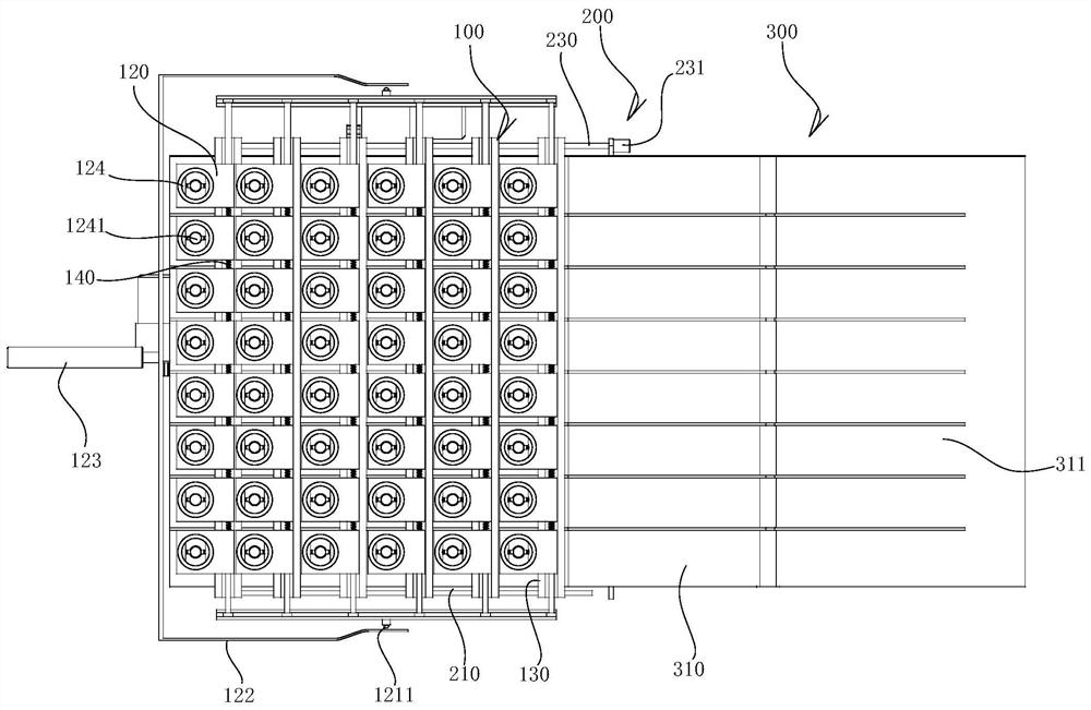
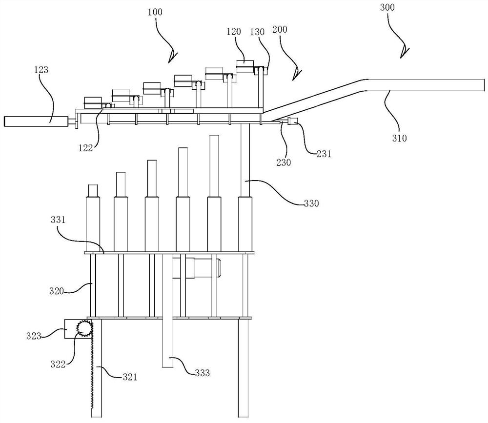
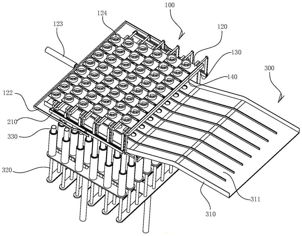
[0039] The following is a detailed description of the thread detection device of the present invention in conjunction with the entire silk roll material supply system:

[0040] Attached below Figure 1 to Figure 34 , A detailed description of the silk roll material supply system of the present invention:

[0041] A silk roll material supply system includes a plurality of rows of roller ...


PUM


Abstract

The invention relates to a silk detection device. The silk detection device comprises a silk guide shuttle plate, wherein the silk guide shuttle plate is arranged in a position of a harness guide pipe, the silk guide shuttle plate is made of transparent organic glass, a plurality of groups of harness channels are formed in the silk guide shuttle plate, the harness channels are arranged in a penetrating mode in the length direction of the silk guide shuttle plate, a photoelectric sensor is arranged at an inlet of the harness channels, the signal collecting end of the photoelectric sensor is pointed to the inlet of the harness channels, silk is guided from the harness guide pipe to the silk guide shuttle plate, and the silk is abutted with the interior of the harness channels. The photoelectric sensor is arranged on the harness channels, so that the spacing between the silk and the harness channels can be effectively collected; when the silk is broken or is used up, a signal is fed backto a control unit by the photoelectric sensor, a control signal is sent by the control unit, so that the system is shut down; then a material roller feeding device is started, so that a new silk material coil is guided to a roller frame, and the new silk material coil is replaced; and then the silk is connected manually.

Description

Technical field [0001] The invention relates to the technical field of silk processing, in particular to a silk thread detection device. Background technique [0002] Before the silk is woven into silk, after the silk raw material is processed through the spinning and dyeing process, it is necessary to use the spinning equipment to wind the dried silk raw material on the silk roller. The silk raw material is wound on the silk roller to effectively prevent the silk from knotting. The problem is that the silk roller is placed on the silk feeding rack, and multiple sets of silk rollers are placed in an array on the silk feeding rack. One end of the silk roller is wound on the warp beam, and after a certain percentage of silk is wound on the warp beam, By starting the weft shuttle machine, the weaving of the weft and warp threads is realized, and the silk cloth is finally formed, thereby completing the initial production of silk. When the above silk roller is placed on the silk feed...

Claims


Application Information

Patent Timeline
Patent Type & Authority Applications(China)
IPC IPC(8): D02H13/08
CPCD02H13/08
Inventor 金绿英
Owner 岳西县长宁织绸有限责任公司
Why Eureka
Try Eureka