
Combined elevator rail clamping device

A combined rail clamp technology, which is applied in elevators, transportation and packaging, etc., can solve the problems of fast wear of rail clamps, unstable control, and difficult deceleration regulation, and achieve reliable control, reliable performance, and stable operation.

Active Publication Date: 2014-02-26
HANGZHOU HUNING ELEVATOR PARTS CO LTD
View PDF5 Cites 15 Cited by
  • Summary
  • Abstract
  • Description
  • Claims
  • Application Information

AI Technical Summary

Problems solved by technology

[0003] The existing rail clamps have problems such as fast wear, unstable control, small boost ratio, and difficult deceleration control.

Method used


Image

  • Combined elevator rail clamping device
  • Combined elevator rail clamping device
  • Combined elevator rail clamping device

Examples


Embodiment 1

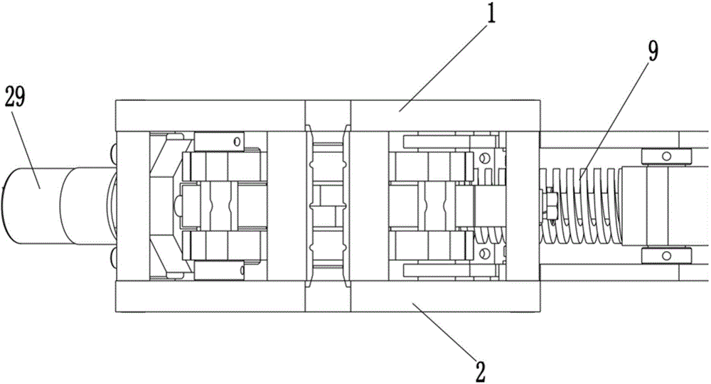
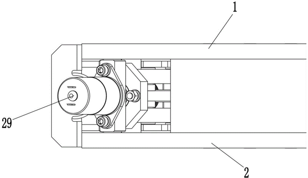
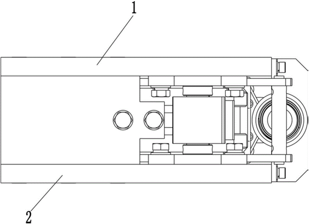
[0028] see Figure 1-9 , the structure of the top plate 1 is the same as that of the bottom plate 2, and the structure of the top plate 1 will be described in detail below.

[0029] The top plate 1 is square, and it is provided with a rectangular notch 1-1, a strip-shaped guide hole 1-2, a guide and positioning hole 1-3, and the rectangular notch 1-1 is located in the middle of one edge of the top plate 1, and the long strip The position of the guide hole 1-2 is close to the notch 1-1, and the centerlines of the two coincide and coincide with the centerline of the edge of the top plate 1. The guide and positioning hole 1-3 is near the other side opposite to the notch 1-1. The part of the guide and positioning hole 1-3 is arc-shaped, and one end of it is bent over an angle. Edges transition smoothly through curved edges.

[0030] The top plate 1 and the bottom plate 2 are arranged in parallel up and down, and the gaps, guide holes, guide and positioning holes between the two ...


PUM


Abstract

The invention discloses a combined elevator rail clamping device which comprises two mounting plates. The two mounting plates are vertically and parallelly laid to form corresponding notches, a translational brake block is arranged between the mounting plates on two sides of each notch, clamping surfaces of the two brake blocks are opposite, a distance is reserved between the clamping surfaces of the two brake blocks, a trigger mechanism and a reset mechanism are arranged between the two mounting plates, the trigger mechanism is an electromagnet, the reset mechanism is a motor, a force-amplifying mechanism is arranged between the two mounting plates, the trigger mechanism triggers the brake blocks to clamp rails towards the opposite side through the force-amplifying mechanism, and the force-amplifying mechanism after rail clamping action is reset by the reset mechanism. By the aid of the combined elevator rail clamping device, excessive speed is controlled by the aid of the trigger mechanism, the reset mechanism and the force-amplifying mechanism, and the elevator rail clamping device is stable in operation and reliable to control. By means of secondary force amplifying, force-amplifying ratio is large, and performances are reliable.

Description

technical field [0001] The invention belongs to the technical field of manufacturing elevator safety components, and in particular relates to a rail clamping device. Background technique [0002] The rail clamp is a braking device that prevents the elevator car from accidentally moving when the door is opened. It is installed on both sides of the elevator car. Under normal conditions, when the elevator is running normally, the device does not work; when the elevator car is in the door-opening and stopping state, due to some fault in the elevator, the elevator runs unexpectedly, causing danger to passengers or goods entering or leaving the elevator. , the device acts and clamps the guide rail, thereby stopping the running elevator car to ensure the safety of passengers and goods. [0003] The existing rail clamps have problems such as fast wear, unstable control, small boost ratio, and difficult deceleration control. Contents of the invention [0004] The invention provid...

Claims


Application Information

Patent Timeline
Patent Type & Authority Applications(China)
IPC IPC(8): B66B5/18
Inventor 邹家春孟红星何新姚荣康王伟陈明星马新峰宋建新
Owner HANGZHOU HUNING ELEVATOR PARTS CO LTD
Learn More