Nuclear fuel element core body removing device

A nuclear fuel element and core technology, applied in the field of nuclear testing, can solve the problems of cladding damage, low efficiency, etc., and achieve the effects of reducing the positioning process, reducing the manufacturing, and reducing the radiation dose value.

Active Publication Date: 2014-02-26
NUCLEAR POWER INSTITUTE OF CHINA
View PDF5 Cites 9 Cited by
  • Summary
  • Abstract
  • Description
  • Claims
  • Application Information

AI Technical Summary

Problems solved by technology

[0004] The purpose of the present invention is to solve the problems that the cladding is easily damaged and inefficient when removing the inner core of the nuclear fuel element cladding, and provides a nuclear fuel element core removal device, which is used for removing the inner core of the nuclear fuel element cladding Avoid secondary damage to cladding and improve core removal efficiency

Method used


Image

  • Nuclear fuel element core body removing device
  • Nuclear fuel element core body removing device
  • Nuclear fuel element core body removing device

Examples


Embodiment 1

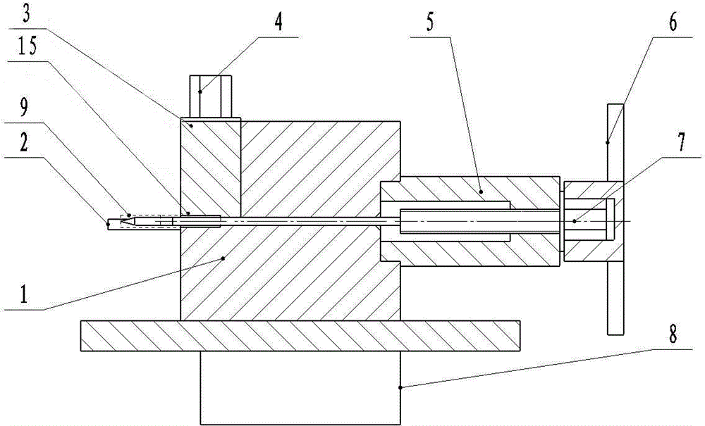
[0025] like figure 1 , figure 2 , image 3 and Figure 5 As shown, a nuclear fuel element core removal device includes a fixed clamp block 1 , a movable clamp block 3 , a thimble 7 and a guide sleeve 5 , and the bottom 10 of the fixed clamp block is arranged on a grooved base 8 . The upper end surface of the fixing clamp block 1 forms a two-step stepped shape, that is, the upper end surface of the fixing clamp block 1 forms a two-step platform with different heights. The movable clamping block 3 is arranged on the lower platform at the horizontal position of the upper end surface of the fixed clamping block 1 and is connected with the fixed clamping block 1, wherein the fixed clamping block 1 and the movable clamping block 3 are connected in a detachable manner, such as using locks, bolts , screws, etc. for connection. The side wall on the side where the horizontal position of the upper end surface of the fixed clamp block 1 is high is indented to form a circular position...

Embodiment 2

[0029]This embodiment is further limited as follows on the basis of Embodiment 1: the movable clamp block 3 of this embodiment is formed with a first positioning screw hole passing through its upper and lower end surfaces, and the upper end surface of the fixed clamp block 1 has a low horizontal position. The concave structure has a second positioning screw hole corresponding to the position of the first positioning screw hole, and the movable clamping block 3 is connected with the fixed clamping block 1 through the clamping bolt 4 passing through the first positioning screw hole and embedded in the second positioning screw hole. In this embodiment, the fixed clamping block 1 and the movable clamping block 3 are connected by clamping bolts 4, which is more convenient for master-slave manipulators to operate, and can further improve work efficiency.

Embodiment 3

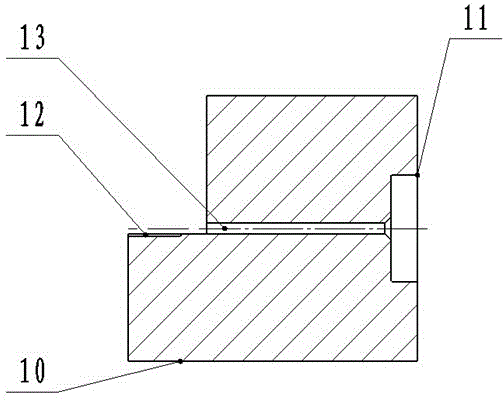
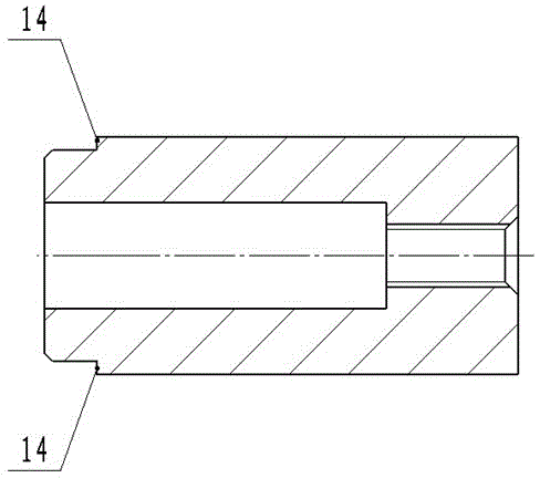
[0031] like figure 1 and Figure 4 As shown, the present embodiment has the following improvements on the basis of embodiment 1 or embodiment 2: the thimble 7 of the present embodiment includes a thimble end 19 connected in sequence, a guide rod 18, a welding rod 17 and a thimble head 16, Wherein, the thimble head 16 is a slender flat-headed rod, and the end 19 of the thimble is provided with an inner hexagonal wrench 6 . An internal thread is formed on the side wall of the inner channel of the guide sleeve 5 , and the guide rod 18 is formed with an external thread matched with the internal thread of the guide sleeve 5 . In the application of this embodiment, one end of the guide rod 18 is embedded in the inner channel of the guide sleeve 15 and connected with the guide sleeve 5 by thread matching, the welding rod 17 passes through the circular channel 13, and the thimble head 16 is embedded in the upper semicircular groove 15 and the lower semicircular groove 12, after the ...


PUM


Abstract

The invention discloses a nuclear fuel element core body removing device including a fixed clamping block, a movable clamping block, an eject pin and a guide sleeve. The upper end face of the fixed clamping block is formed in a two-step stepped shape; the movable clamping block is arranged on a region at a lower horizontal position of the upper end face of the fixed clamping block and is connected with the fixed clamping block; the end part of one end of the guide sleeve is connected with the side wall of one side at a higher horizontal position of the upper end face of the fixed clamping block. The lower end face of the movable clamping block is provided with an upper semicircular groove, the upper end face of the fixed clamping block is provided with a lower semicircular groove corresponding to the upper semicircular groove position, the fixed clamp block is provided with a circular pore channel for communicating the lower semicircular groove with a guide sleeve internal channel, the center lines of the upper semicircular groove, the lower semicircular groove, the circular pore channel and the guide sleeve internal channel are justified, and one end of the eject pin successively passes through the guide sleeve internal channel and the circular pore channel. By adopting the above structure, the nuclear fuel element core body removing device has compact structure, is easy to transport, can improve the removal efficiency of a core body while being used for removing a core body in a cladded shell, and can avoid the cladded shell from being suffered from secondary damage.

Description

technical field [0001] The invention relates to auxiliary equipment in the field of nuclear testing, in particular to a nuclear fuel element core removal device. Background technique [0002] The research on cladding after irradiation must first remove the fuel core inside the cladding. Under the action and influence of high temperature, gas-solid fission products and high-energy particles, the core will cause swelling, thermal stress, lattice destruction and corrosion, etc. Destruction, part of the core body and the cladding are bonded and so on. In the heat chamber, it is difficult to remove the fuel core only by relying on the master-slave manipulator. [0003] At present, there are two main methods for removing the core body. The most commonly used method is the thimble inertia removal method, that is, the cladding is fixed with a spacer, the thimble falls from above, and the core is removed by using the inertia of the thimble. The main disadvantage of this method is th...

Claims


Application Information

Patent Timeline
Patent Type & Authority Applications(China)
IPC IPC(8): G21C19/36
CPCY02E30/30
Inventor 张帅顾剑涛蒋国富陈军许德强吴拥军王健
Owner NUCLEAR POWER INSTITUTE OF CHINA
Why Eureka
Try Eureka