Encoders, Encoder Installation Methods, Encoder Replacement Methods, and Motor Units
An installation method and an encoder technology, which are applied in the field of encoders, can solve problems such as the difficulty in the concentricity of the motor shaft and the concave structure, and the cost of man-hours, and achieve the effect of simplifying installation or replacement operations
- Summary
- Abstract
- Description
- Claims
- Application Information
AI Technical Summary
Problems solved by technology
Method used
Image

Examples
no. 1 approach
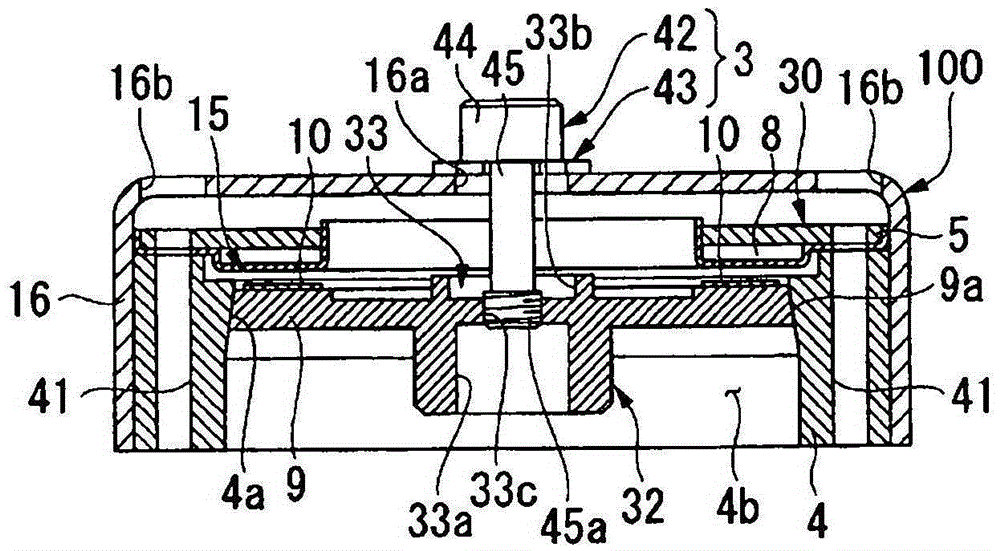
[0039] An encoder is a device that detects the rotation speed and rotation speed of a rotating body (motor device) such as a motor. figure 1 It is a cross-sectional view showing the overall structure of the encoder 100 according to the first embodiment, and is a view showing a state before being mounted on a motor. Such as figure 1 As shown, the encoder 100 has a mounting member 3, a housing (main body) 4, a detection portion (substrate portion) 30, a disc portion 15, and a cover mounted on the housing 4 in a state covering the detection portion 30. part (body part) 16 .
[0040] The detection unit 30 has a detection substrate 5 and an optical sensor (detection unit) 8 . In one example, the detection substrate 5 is a circular plate-shaped member when viewed from above. In the present embodiment, the detection unit 30 irradiates light to the light reflection pattern (dial) 10 formed on the disc portion (rotation unit) 15, and the light sensor 8 detects the reflected light fr...
no. 2 approach
[0083] Next, the structure of the second embodiment of the present invention will be described. In addition, the difference between the present embodiment and the first embodiment is that a retaining ring is not used as an attachment member, and other configurations are the same. Therefore, in the following description, the description of the same members and structures as those of the first embodiment will be omitted or simplified.
[0084] Figure 7 is a diagram showing the overall configuration of the encoder of this embodiment, Figure 7 (a) is a cross-sectional view of the encoder, Figure 7 (b) is a plan view showing the structure of the main part of the encoder.
[0085] Encoder 200, such as Figure 7 As shown in (a), it has the attachment member 50, the case 4, the detection part 30, the disc part 15, and the cover part 16 similarly to the structure of 1st Embodiment.
[0086] The mounting member 50 of the present embodiment is constituted by a fixing member 51 . ...
PUM
 Abstract
Description
Claims
Application Information
 - R&D
- Intellectual Property
- Life Sciences
- Materials
- Tech Scout
- Unparalleled Data Quality
- Higher Quality Content
- 60% Fewer Hallucinations
Browse by: Latest US Patents, China's latest patents, Technical Efficacy Thesaurus, Application Domain, Technology Topic, Popular Technical Reports.
© 2025 PatSnap. All rights reserved.Legal|Privacy policy|Modern Slavery Act Transparency Statement|Sitemap|About US| Contact US: help@patsnap.com