Low speed safety protection drilling jig

A technology for safety protection and drilling jigs, applied in clamping, manufacturing tools, supports, etc., can solve problems such as damaged motors, increased current, and drill bits stuck to workpieces

Active Publication Date: 2016-11-09
江苏索达重工有限公司
View PDF9 Cites 0 Cited by
  • Summary
  • Abstract
  • Description
  • Claims
  • Application Information

AI Technical Summary

Problems solved by technology

[0002] In the prior art, one end of the clamp on the drilling tool is connected to the power output shaft, and the other end is used to clamp the drill bit for drilling. Traditionally, the clamps used for the drilling tool are generally of integral structure. When in use, the drilling tool clamp Hold the drill bit and rotate it to drill holes driven by the power output shaft. With the traditional integral structure, when the drill bit gets stuck or encounters a large resistance, the current will suddenly increase, which may damage the motor on the one hand, and damage the motor on the other. On the one hand, it may also cause the drill bit to jam the workpiece and damage the drill bit

Method used


Image

  • Low speed safety protection drilling jig

Examples


Embodiment Construction

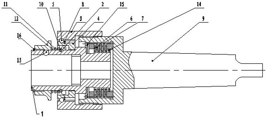
[0015] The low-speed safety protection drilling jig of the present invention will be further described in detail below in conjunction with the accompanying drawings and specific embodiments.

[0016] As shown in the figure, the low-speed safety protection drilling jig of the present invention includes an external gear sleeve 1 and an internal gear sleeve 9 sleeved on the outer surface of the outer circumference of the rear end of the external gear sleeve; the rear end of the external gear sleeve 1 is provided with A shaft circlip 14, the front end of the inner gear sleeve 9 is provided with a circlip 15 for holes, the outer surface of the front circumference of the outer gear sleeve 1 is covered with a positioning steel ball sleeve 12, and the outer gear sleeve 1 is provided with a The front retaining ring 16 of the limit positioning steel ball sleeve 12; the positioning steel ball 13 in the steel ball placement cavity on the external gear sleeve 1 is arranged between the posit...


PUM


Abstract

The invention discloses a low-rpm drilling fixture with a safety protection function. The low-rpm drilling fixture with the safety protection function comprises an outer tooth shaft sleeve and an inner tooth shaft sleeve. The outer circumferential surface of the front end of the inner tooth shaft sleeve is connected with an adjusting nut. The front end of the outer tooth shaft sleeve is provided with a chuck. Outer teeth are arranged on the outer circumference of the rear end of the outer tooth shaft sleeve. The outer tooth shaft sleeve is sleeved with inner tooth friction plates. Inner teeth are arranged in the inner tooth shaft sleeve and are sleeved with outer tooth friction plates. The outer tooth friction plates and the inner tooth friction plates are located between a limiting end face of the outer tooth shaft sleeve and a limiting end face of the inner tooth shaft sleeve. When the outer tooth shaft sleeve and the inner tooth shaft sleeve squeeze each other, the outer tooth friction plates and the inner tooth friction plates are axially pressed tightly on the two limiting end faces. Through the structure, the inner tooth shaft sleeve is driven to press tightly or loosen the friction plates through the adjusting nut so that the friction moment between the outer tooth shaft sleeve and the inner tooth shaft sleeve can be increased or decreased, and the low-rpm drilling fixture can play roles in transmitting moment and carrying out overload safety protection. Consequently, current surges are completely avoided, and the phenomenon that a motor or a drill bit is damaged is prevented completely.

Description

technical field [0001] The invention relates to a jig for a drilling tool, in particular to a low-speed safety protection drilling jig. Background technique [0002] In the prior art, one end of the clamp on the drilling tool is connected to the power output shaft, and the other end is used to clamp the drill bit for drilling. Traditionally, the clamps used for the drilling tool are generally of integral structure. When in use, the drilling tool clamp Hold the drill bit and rotate it to drill holes driven by the power output shaft. With the traditional integral structure, when the drill bit gets stuck or encounters a large resistance, the current will suddenly increase, which may damage the motor on the one hand, and damage the motor on the other. On the one hand, it may also cause the drill bit to jam the workpiece and damage the drill bit. Contents of the invention [0003] The technical problem to be solved by the present invention is to provide a low-speed safety prot...

Claims


Application Information

Patent Timeline
Patent Type & Authority Patents(China)
IPC IPC(8): B23Q3/00
CPCB23Q3/12
Inventor 张强曹量力
Owner 江苏索达重工有限公司
Why Eureka
Try Eureka