A positioning device for workpiece fixture in ion beam polishing equipment

A workpiece fixture and positioning device technology, applied in the field of workpiece positioning devices, can solve the problems of severe vibration of the workpiece, difficulty in ensuring position accuracy, influence of the workpiece itself and positioning effect, etc., to achieve vibration elimination, simple action, and easy assembly and adjustment Effect

Inactive Publication Date: 2016-01-20
INST OF OPTICS & ELECTRONICS - CHINESE ACAD OF SCI
View PDF1 Cites 2 Cited by
  • Summary
  • Abstract
  • Description
  • Claims
  • Application Information

AI Technical Summary

Problems solved by technology

Although this method can realize the positioning of the fixture, in the actual operation process, first of all, it is necessary to ensure that the two chucks 21 are aligned in the Z direction and the Y direction. Since the left and right chucks are two independent parts with a certain distance, the It is difficult to guarantee its position accuracy during the process; in addition, during the clamping process, due to the large clamping force (otherwise the positioning effect cannot be achieved), the workpiece will vibrate violently, which will have a certain impact on the workpiece itself and the positioning effect. Impact

Method used


Image

  • A positioning device for workpiece fixture in ion beam polishing equipment
  • A positioning device for workpiece fixture in ion beam polishing equipment
  • A positioning device for workpiece fixture in ion beam polishing equipment

Examples


Embodiment Construction

[0052] In order to make the object, technical solution and advantages of the present invention clearer, the present invention will be described in further detail below in conjunction with specific embodiments and with reference to the accompanying drawings.

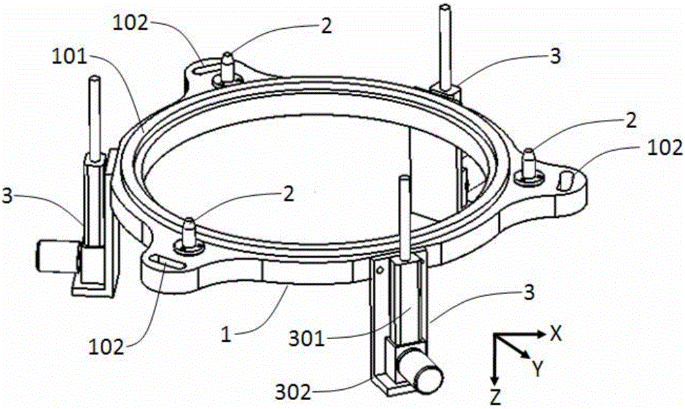
[0053] image 3 Shown is a schematic diagram of the structure of the datum used as the datum in the present invention, the datum used as the datum includes an annular positioning disc 1 , three positioning pins 2 and three sets of lifting devices 3 . see also Figure 4 , Figure 5 As shown, the annular positioning plate 1 is made of No. 45 steel, and has been quenched and tempered. There are raised circular steps on its upper surface (-Z direction), and the upper surface of the steps (-Z direction) has been ground. It can reach 0.01mm, and the height is H, which is used as the horizontal positioning plane 101 on the annular positioning disc; along the outer circumference of the annular positioning disc 1, there are thre...


PUM


Abstract

The invention discloses a positioning device for a workpiece fixture in ion beam polishing equipment. The scheme includes that an annular positioning plate and the chuck type workpiece fixture interact with each other, and the annular positioning plate used as a positioning reference is horizontally and fixedly mounted, so that the workpiece fixture can be positioned by the positioning device. The positioning device is characterized in that a convex horizontal positioning plane, lifting devices and positioning pins are arranged on the upper surface of the annular positioning plate, the lifting devices and the positioning pins are symmetrically arranged along the peripheral edge of the positioning plate, a positioning plane which can cling to the horizontal positioning plane on the positioning plate is arranged on the fixture, and positioning holes which can be in one-to-one correspondence with the positioning pins on the positioning plate are formed in the fixture. The lifting devices lift the fixture with a clamped workpiece to a certain altitude and then slowly descend, so that the two positioning planes can completely cling to each other, all the positioning pins can be inserted into the positioning holes, and the workpiece fixture can be positioned. The positioning device has the advantages that positioning references are arranged on the same component, so that the workpiece fixture can be easily adjusted and can be completely positioned under the effect of the gravity of the fixture as long as the references are effectively adjusted, and the positioning device is simple in action; the positioning movement speed is controllable, so that positioning operation can be slowly carried out, and vibration can be greatly reduced and eliminated.

Description

technical field [0001] The invention belongs to the field of precision optical parts processing, and relates to a workpiece positioning device in ion beam polishing equipment. Background technique [0002] Ion beam polishing uses the principle of ion sputtering to bombard the surface of the workpiece with a Gaussian distribution of ion beams to achieve the purpose of removing materials. high merit. The precision of ion beam polishing can reach the nanometer level, and it is an important means for ultra-precision optical element processing, especially for lens processing in exposure systems in the field of microelectronic lithography. [0003] The accuracy of ion beam polishing is not only related to the removal function, the control accuracy of the actuator, and the processing method, but also related to the positioning accuracy of the workpiece. For the layout form where the ion source is polished under the workpiece, the workpiece positioning includes center positioning ...

Claims


Application Information

Patent Timeline
Patent Type & Authority Patents(China)
IPC IPC(8): B24B41/06
CPCB24B1/00B24B41/06
Inventor 付韬韬张海波王安定
Owner INST OF OPTICS & ELECTRONICS - CHINESE ACAD OF SCI
Why Eureka
Try Eureka