Daylight lamp lampholder

A technology for fluorescent lamps and lamp sockets, which is applied to lighting devices, lighting device parts, lighting auxiliary devices, etc., can solve the problems of inaccurate positioning of contact points, poor contact between spring contacts and lamp pins, etc. Convenience, Contact Guarantee, Improved Contact Effect

Inactive Publication Date: 2014-03-05
舟山职业技术学校 +1
View PDF10 Cites 0 Cited by
  • Summary
  • Abstract
  • Description
  • Claims
  • Application Information

AI Technical Summary

Problems solved by technology

[0003] In view of the above-mentioned deficiencies, the technical problem to be solved by the present invention is mainly the problem of poor contact between the spring contact piece and the lamp pin, including the problem of contact between t

Method used


Image

  • Daylight lamp lampholder
  • Daylight lamp lampholder
  • Daylight lamp lampholder

Examples


Embodiment Construction

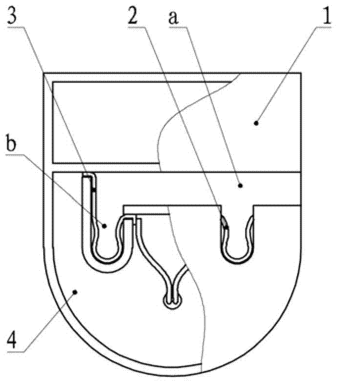
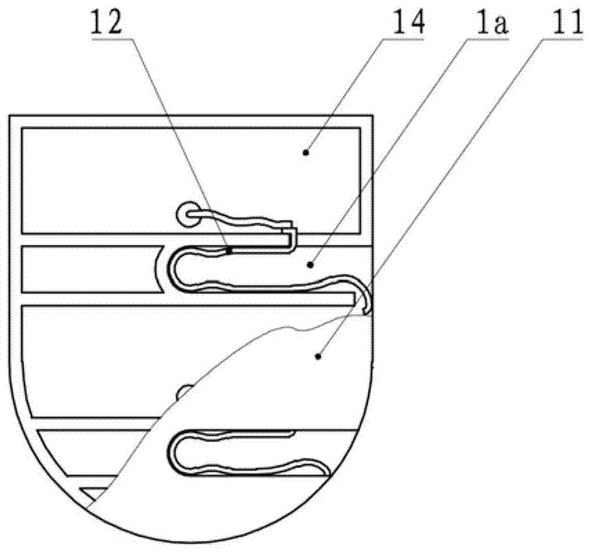
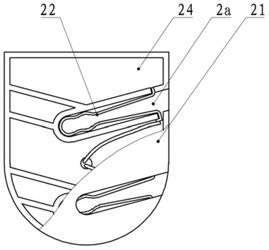
[0016] 1. Fluorescent lamp holder, such as figure 1 As shown, there is a housing composed of a housing base 4 and a panel 1, and a horizontal F-shaped linear translation chute is formed on the housing base, and there is a groove on the panel that is consistent with the F-shaped chute on the housing base. Holes, the two are combined to form a shell. In the housing seat, one end of the transverse groove a runs through the side wall of the housing seat, and the other end is turned downwards into a longitudinal groove b, and there is another longitudinal groove at a symmetrical position relative to the vertical line of the longitudinal groove. The distance between the two longitudinal grooves is the distance between the two lamp pins corresponding to the specification of the fluorescent lamp matched with the lamp holder. The lower ends of the two longitudinal grooves are semicircular, and each has a U-shaped spring contact piece installed therein. in the slot. Wherein the sprin...


PUM


Abstract

The invention discloses a daylight lamp lampholder which is provided with a shell body. Rectilinear translation sliding grooves (a and b) along a shell body panel (1) are formed in the shell body and are provided with notches in the side wall of the shell body. Spring contacts (2 and 3) in contact with lamp feet are formed in the sliding grooves. Final sections, in the shell body, of the sliding grooves are provided with two paths respectively containing two lamp feet. The spring contacts are distributed on the two sides of the two final sections of the sliding grooves. According to the daylight lamp lampholder, the two lamp feet are provided with respective final sections of the sliding grooves, and the contacts are arranged on the two sides of the sliding grooves, so that that two lamp feet can slide to bottom ends of the grooves along the sliding grooves for location, the sliding progress does not need controlling. Moreover, the contacts are arranged on the two sides, so that the contact range of the contacts and the lamp feet is large, and the contacts compress the lamp feet from the two sides, so that contact is improved. Compared with the prior art, the daylight lamp lampholder brings convenience to the installation and the detachment of a lamp tube, and well ensures the contact of the lamp feet and the contacts.

Description

technical field [0001] The invention relates to a fluorescent lamp holder, in particular to a fluorescent lamp pin insertion structure in the fluorescent lamp holder. Background technique [0002] Fluorescent lamps generally refer to lamps composed of lamp tubes and lamp caps at both ends. Fluorescent lamps and LED tube lamps are commonly used. The lamp holder of the fluorescent lamp has a lamp pin plug-in structure, and the plug-in structure has a shell and a pole piece that contacts the lamp pin and conducts electricity. The fluorescent lamp holders used in the early days were pin-type lamp holders. There were two jacks on the shell panels, and pole piece pins were arranged in the jacks. One of the two lamp holders was connected to the bottom plate by an axial spring. When installing a fluorescent lamp, it is used to compress the spring so that the lamp pin can be inserted into the socket. It is inconvenient to align the holes when installing the lamp tube, which brings ...

Claims


Application Information

Patent Timeline
IPC IPC(8): F21V21/002
Inventor 倪志伟袁良红倪皓旻
Owner 舟山职业技术学校
Why Eureka
Try Eureka