
Stripper and packing apparatuses

Active Publication Date: 2021-04-01
TECH PRECESS TECH INC
View PDF0 Cites 0 Cited by
  • Summary
  • Abstract
  • Description
  • Claims
  • Application Information

AI Technical Summary

Benefits of technology

The patent describes a packing system for a fluidized bed that includes a plurality of packing elements. The packing elements can have different sizes, angles of inclination, and spacing between them. The system also includes a hollow tapered body to facilitate contact between solids and fluids. The technical effects of the invention include improved contact between solids and fluids, increased efficiency of the fluidized bed, and reduced pressure drop.

Problems solved by technology

In fact, insufficient stripping results in the reactor effluent remaining on and in between the catalyst particles so that during the regeneration step an additional combustion load is imposed upon the regenerator with excessive heat production beyond the heat needed to drive the catalytic reaction.
As a result, the combustion of entrained hydrocarbon vapors into the regenerator represents a loss in final yield of converted product.
In a FCC stripper vessel, it tends to be difficult to control the travel of the catalyst particles and to avoid partial de-fluidization linked with channeling (direct passage of large bubbles through the deep fluidized bed or preferential down flow of catalyst towards one side of the vessel) and with back-mixing (down flow of poorly fluidized particles or even recirculation of such particles, especially in the region of the stripping chamber wall).
Thus, the average stripping time of deactivated catalyst particles and the quality of contact between catalyst particulates and gaseous fluid are difficult to control.
Additionally, any mal distribution or preferential flow pattern of gas vapors and catalyst particles can limit the catalyst circulation capability through the stripper vessel.
Generally, an excessive amount of steam is required in such scenarios to achieve sufficient stripping efficiency.
The excess steam increases the gas and liquid load on equipment connected to the stripper.
For example, the excess steam can increase the quantity of sour water produced per pound of hydrocarbon processed, as well as increase the operating costs for producing and processing the excess steam.
Moreover, the device reduces the back-mixing and channeling of the particles and the formation of solid or gaseous pockets within the stripping chamber.
Once initiated, channeling is very difficult to stop and there may be almost complete bypassing of the two phases.
Once a “clear stream” of either phase is formed the existing packing is not very effective at redistributing it, inspecting the actual packing shows that a single phase can travel considerable distances within, and between, the layers.
Once they reach the next layer there is limited potential for redistribution and the single phase will continue and potentially grow.
Another limitation of the existing design is the two directional arrangement of the blades which provides approximately 95% open cross-sectional area and limits radial mixing.
As a result of this, upward flowing steam is also not uniformly distributed within the elements and when it leaves the top of the packing, which further reduces the usage of the steam to strip the hydrocarbons
The active catalyst flow region close to the SCSP entrance results in high catalyst velocity because the catalyst is only flowing through a reduced stripper cross-sectional area.
Existing packing designs are quite dense in terms of blade count and there is significant weight that must be supported.
However, it has often not produced the expected performance improvements; raw stripping efficiency (manifested as H2 in coke and regenerator temperature), pressure build up and steam consumption.
Current structured packing elements have various limitations, for example, reduced mixing of the stripping gas and catalyst because a portion of gas stream tends to flow up along the underside of planar portions or blades and a portion of catalyst stream tends to flow down the top side of the blade with little or no interaction between the gas and catalyst.
Despite the flow direction of each element or layer of elements being 90° oriented to each other the continuous blade surfaces do not provide good re-distribution of catalyst and gas throughout the depth of the fluidized bed.

Method used


Image

  • Stripper and packing apparatuses
  • Stripper and packing apparatuses
  • Stripper and packing apparatuses

Examples


Embodiment Construction

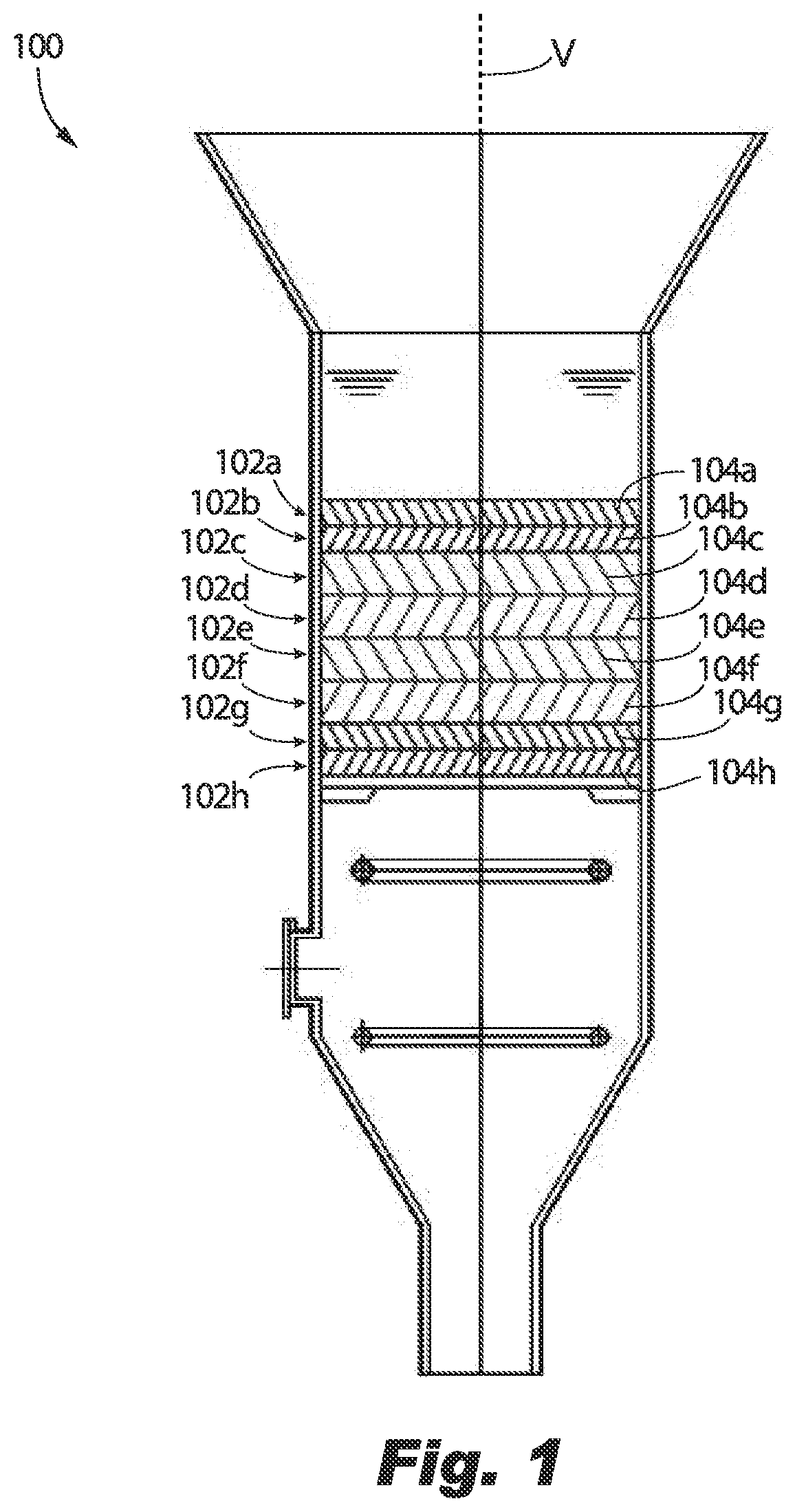
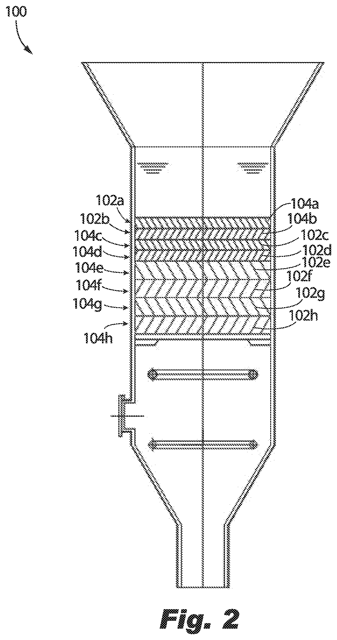
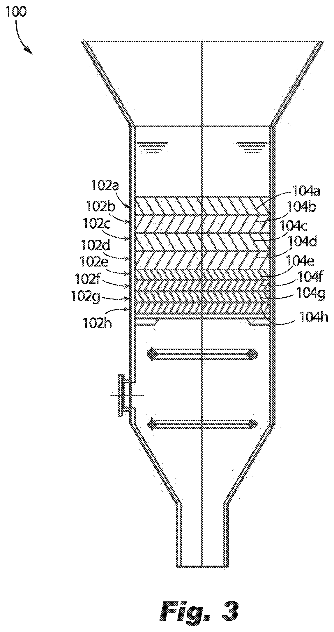
[0063]Embodiments of the disclosure are described more fully hereinafter with reference to the accompanying drawings, in which example embodiments of the disclosure are shown. This disclosure may, however, be embodied in many different forms and should not be construed as limited to the example embodiments set forth herein; rather, these embodiments are provided so that this disclosure will be thorough and complete, and will fully convey the scope of the embodiments to those skilled in the art. Like numbers refer to like, but not necessarily the same or identical, elements throughout. For purposes of explanation and illustration, and not limitation, a schematic representation of an exemplary embodiment of a packing system configured to facilitate contact between solids and fluids in a fluidized bed constructed in accordance with embodiments of the present disclosure is shown in FIG. 1 and is designated generally by reference character 100. Other embodiments of packing systems in acc...


PUM


Abstract

A packing system includes a first packing element layer including a plurality of blades and a second packing element layer including a plurality of blades. The packing system includes intra-layer variation and / or inter-layer variation. Intra-layer variation includes (i) varying spacing between blades within the first and / or the second packing element layer, (ii) varying sizes of the blades within the first and / or the second packing element layer, and / or (iii) varying angle of inclination of the blades within the first and / or second packing element layer. Inter-layer variation includes the blades of the first packing layer having a first spacing, a first size and a first angle of inclination, and the blades of the second packing layer having a second spacing, a second size, and a second angle of inclination. The second spacing, size, and / or angle of inclination is different from the first spacing, size, and / or angle of inclination.

Description

CROSS-REFERENCE TO RELATED APPLICATIONS[0001]This application claims priority to U.S. Provisional Patent Application Ser. No. 62 / 675,975, filed May 24, 2018, which is incorporated herein by reference in its entirety.BACKGROUND OF THE INVENTION1. Field of the Invention[0002]The present disclosure relates to fluidized beds in which solids and fluids flow in a countercurrent or co-current relationship. More particularly, the embodiments disclosed herein are directed to a Fluid Catalytic Cracking “FCC” stripper apparatus and internals, and more specifically to structured packing elements to facilitate contact between the solids and fluids in the fluidized bed.2. Description of Related Art[0003]The Fluidized Catalytic Cracking (FCC) process is a chemical process commonly used in oil refineries, the purpose of which is to convert heavy, high molecular weight hydrocarbon materials into lighter lower molecular weight hydrocarbon fractions. In this type of process a hydrocarbon feedstock is ...

Claims


Application Information

Patent Timeline
IPC IPC(8): B01J8/34B01J19/32
CPCB01J8/34B01J19/32B01J2219/3325B01J2219/32234B01J2219/32213C10G11/18B01J2219/32262B01J2219/32237B01J2219/32279B01J2219/32268B01J2219/32272B01J2219/32408
Inventor MARCHANT, PAULSINGH, RAJ KANWARCARTER, MILLARD ALAMATHELLIS, ROBERTODHARIA, DILIP
Owner TECH PRECESS TECH INC
Learn More