Wire forming unit and welding torch with wire forming unit

A forming unit and welding wire technology, applied in the direction of manufacturing tools, welding equipment, arc welding equipment, etc., can solve the problem that the contact sleeve is not suitable for reliable contact with the welding wire, the contact sleeve contact cannot be improved reliably, and the contact point contact force cannot be achieved reliably. and other problems, to achieve the effect of stable guarantee, improved contact and welding quality assurance

Active Publication Date: 2020-09-11
FRONIUS INTERNATIONAL GMBH
View PDF10 Cites 0 Cited by
  • Summary
  • Abstract
  • Description
  • Claims
  • Application Information

AI Technical Summary

Problems solved by technology

The problem in this case is that the welding wire again experiences an uncontrolled curvature in the absolutely possibly long hose assembly, whereby the contact in the contact sleeve cannot be reliably improved
This device is not suitable for reliable contact of the contact sleeve with the welding wire in the welding torch itself, because in order to determine the position and contact force of the contact point in the contact

Method used


Image

  • Wire forming unit and welding torch with wire forming unit
  • Wire forming unit and welding torch with wire forming unit
  • Wire forming unit and welding torch with wire forming unit

Examples


Embodiment Construction

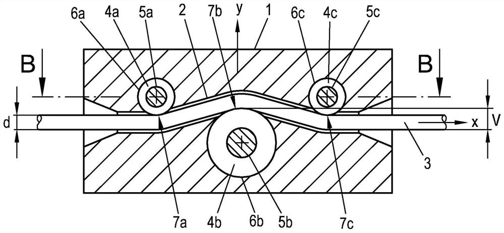
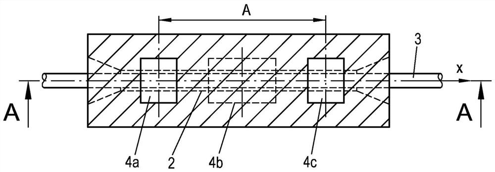
[0028] exist figure 1 A side view section (section A-A) of the wire forming unit 1 of the present invention is shown in , and in figure 2A top view section (section B-B) of the wire forming unit 1 is shown in FIG. Provided in the wire forming unit 1 is a through channel 2 for guiding the welding wire 3 in a longitudinal direction x (indicated by the movement arrow) which substantially corresponds to the direction of movement of the welding wire 3 . However, channel 2 can of course also be designed to be larger than the figure 1 and 2 is much larger than shown in . For example, the wire forming unit 1 can be designed as a hollow housing, wherein the entire cavity forms the channel 2 . However, guiding the welding wire 3 in a narrow channel 2 can be beneficial for the penetration of the welding wire 3 . In any event, the channel 2 is preferably constructed so large that the welding wire 3 does not touch the channel walls of the channel 2 at any point when being guided, i...


PUM


Abstract

The aim of the invention is to achieve a reliable constant contact in a welding torch with a contact sleeve with a wire forming unit and to reduce the frictional forces for the wire forming process. This is achieved in that three ball bearing-mounted rollers (4a, 4b, 4c) are arranged one behind the other in the longitudinal direction (x) of the welding torch (10) in the wire forming unit (1). Thecentral roller (4b), when viewed in the longitudinal direction (x), is offset in the wire forming unit (1) relative to the two outer rollers (4a, 4c), when viewed in the longitudinal direction (x), bya transverse offset (V) in a transverse direction (y) transverse to the longitudinal direction (x) in order to form a zig-zag-shaped path for the welding wire (3) through the wire forming unit (1), wherein the axial distance (A) between the two outer rollers (4a, 4c) when viewed in the longitudinal direction (x) is maximally 35 mm, preferably maximally 30 mm, more preferably maximally 20 mm.

Description

technical field [0001] The invention relates to a wire forming unit for forming a welding wire for a welding torch with a contact sleeve and a welding torch with a contact sleeve, the welding torch having such a welding wire forming unit. Background technique [0002] Welding methods using molten electrodes are well known. It is also known here to use the welding wire itself as an electrode, by means of a wire feeding unit feeding the welding wire to a welding torch in which a contact sleeve with an electrical potential is arranged. The wire contacts the contact sleeve as it is fed through the torch, whereby when the electric welding circuit is closed via the welding arc formed between the wire and the workpiece to be welded (which is usually at ground potential), a welding current can be passed through The contact sleeve flows over the wire. Examples of such welding methods are MIG (MIG) and MIG (MAG), wherein a shielding gas is additionally supplied to the welding site. ...

Claims


Application Information

Patent Timeline
IPC IPC(8): B23K9/133
CPCB23K9/133B23K9/122
Inventor A·莱昂哈特伯格W·哈伯勒尔D·普拉泽K·奥伯恩多弗
Owner FRONIUS INTERNATIONAL GMBH
Why Eureka
Try Eureka