Double-sound-track ultrasonic heat meter

An ultrasonic and heat meter technology, which is applied in the field of dual-channel ultrasonic heat meters, can solve problems such as poor adaptability, decreased measurement accuracy, and failure to use normally, and achieve accurate measurement results, reduced correction difficulty, and accurate measurement results.

Inactive Publication Date: 2014-03-05
RUINA INTELLIGENT EQUIP CO LTD
View PDF3 Cites 5 Cited by
  • Summary
  • Abstract
  • Description
  • Claims
  • Application Information

AI Technical Summary

Problems solved by technology

[0003] Domestic large-diameter ultrasonic heat meters are usually monophonic. The main disadvantage of monophonic is that the fluid in the flowmeter’s measurement cavity must meet the requirements of stable flow and ideal flow. Once the velocity distribution of the flow field deviates or Irregularity, resulting in greatly reduced measurement accuracy and cannot be used normally
[0004] Other multi-channel channel arrangement is relatively simple equal division, that is, the section of the circular tube is divided into three equal parts in the diameter direction, and the position of the channel is 0.167DN from the axis. This arrangement does not conform to the fluid flow. The characteristics of the installation environment are not good, the adaptability is not good, the measurement accuracy is not significantly improved, and the effect is not good

Method used


Image

  • Double-sound-track ultrasonic heat meter
  • Double-sound-track ultrasonic heat meter
  • Double-sound-track ultrasonic heat meter

Examples


specific Embodiment approach

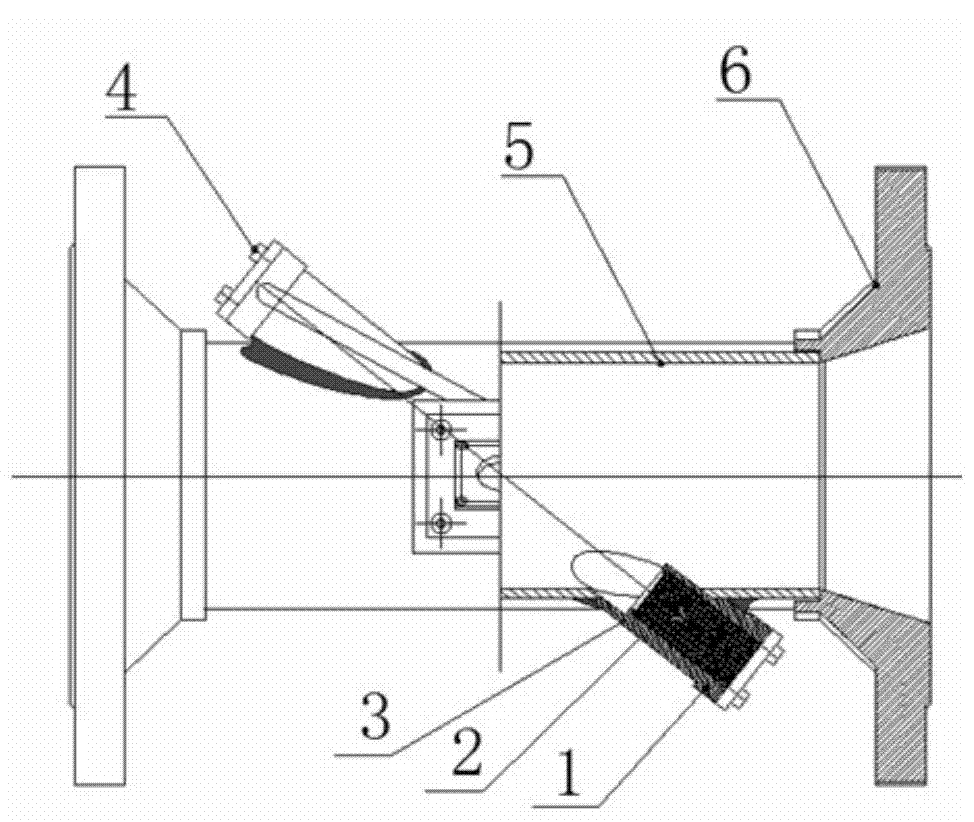
[0018] Two-channel ultrasonic heat meter of the present invention, its preferred embodiment is:

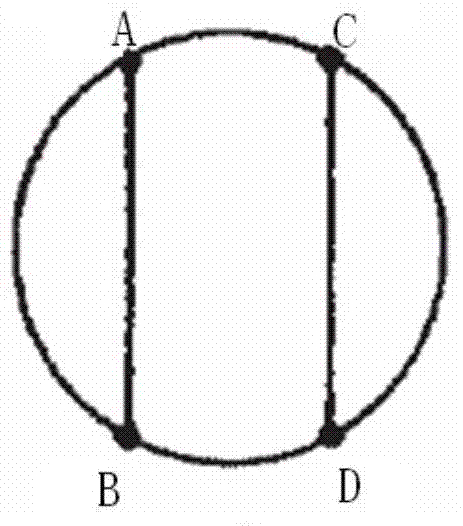
[0019] Including the pipe body, the wall of the pipe body is provided with four installation ports, and each installation port is respectively equipped with an ultrasonic transducer, and the four ultrasonic transducers are opposite to each other to form a sound channel, and two sound channels The axes of the channels are parallel to each other, have the same length and are symmetrically distributed on both sides of the axis of the tube body, and the axes of the two channels are at the same distance from the axis of the tube body.

[0020] The included angle between the axes of the two sound channels and the axis of the pipe body is less than 90 degrees.

[0021] Viewed from the end face of the pipe body, each ultrasonic transducer protrudes 1 / 4 to 1 / 3 of the inner cavity of the pipe.

[0022] A transducer mounting seat is welded on the pipe body at the installation port, and the ...

specific Embodiment

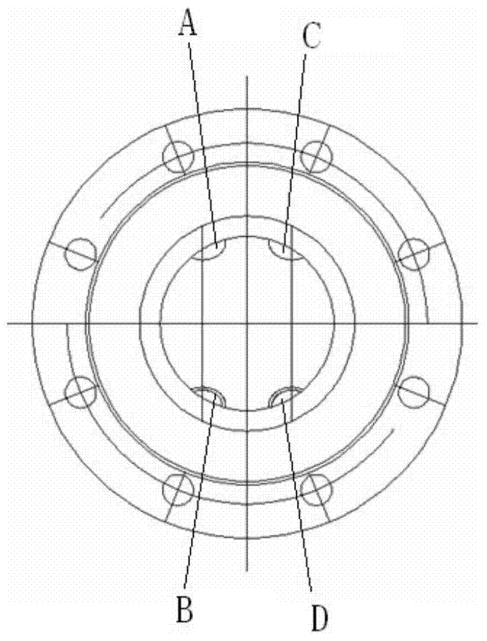
[0029] Such as Figure 1a , Figure 1b , 2a , 2b, four inclined holes are precisely machined on the pipe body, two of which are coaxial; based on the inclined holes, four transducer mounting seats are welded on the steel pipe; and then the flanges are welded on both ends of the pipe body ; Put the ultrasonic transducer assembly into it, and cover the transducer gland.

[0030] Viewed from the end face of the tube body, the first transducer is coaxial and opposite to the second transducer, and the third transducer is coaxial and opposite to the fourth transducer; the signals of the two channels are independent of each other, in the required position.

[0031] The transducer assembly is coaxially fixed in the transducer mounting seat, and is pressed with a gland so that there will be no relative displacement after the two are assembled. In addition, the transducer assembly contains an O-ring, which makes the flowmeter flow during the measurement process. , there will be no le...


PUM


Abstract

The invention discloses a double-sound-track ultrasonic heat meter. The ultrasonic heat meter comprises a tube body, four installing ports are formed in the wall of the tube body, an ultrasonic transducer is installed on each installing port, the four ultrasonic transducers are arranged opposite in pairs, each two opposite ultrasonic transducers form a sound track, the two sound tracks with axes mutually parallel and lengths equal are symmetrically distributed on the two sides of the axis of the tube body, and the distances between the axes of the two sound tracks and the axis of the tube body are equal. In this way, the ultrasonic transducers are basically arranged in the positions where a flow field velocity is very close to mean flow velocity of the water velocity on the cross section in a tube, correction difficulty of measurement errors by a computer matched with a flowmeter can be greatly reduced, and therefore a final measurement result is accurate.

Description

technical field [0001] The invention relates to an ultrasonic heat meter, in particular to a two-channel ultrasonic heat meter. Background technique [0002] Large-diameter ultrasonic heat meters are generally divided into monophonic and multi-channel. [0003] Domestic large-diameter ultrasonic heat meters are usually monophonic. The main disadvantage of monophonic is that the fluid in the flowmeter’s measurement cavity must meet the requirements of stable flow and ideal flow. Once the velocity distribution of the flow field deviates or Irregularity, resulting in greatly reduced measurement accuracy and cannot be used normally. [0004] Other multi-channel channel arrangement is relatively simple equal division, that is, the section of the circular tube is divided into three equal parts in the diameter direction, and the position of the channel is 0.167DN from the axis. This arrangement does not conform to fluid flow. It is not suitable for occasions where the installatio...

Claims


Application Information

Patent Timeline
Patent Type & Authority Applications(China)
IPC IPC(8): G01K17/06
Inventor 巫军华王兆杰
Owner RUINA INTELLIGENT EQUIP CO LTD
Why Eureka
Try Eureka