Polishing machine for shaft

A polishing machine and polishing wheel technology, which is applied in the field of polishing machines, can solve problems such as shaft surface bruises and low production efficiency, and achieve the effect of ensuring polishing quality

Inactive Publication Date: 2014-03-12
ZHEJIANG TAISHAN HEAVY MACHINERY
View PDF6 Cites 5 Cited by
  • Summary
  • Abstract
  • Description
  • Claims
  • Application Information

AI Technical Summary

Problems solved by technology

Existing ordinary shaft polishing machines often only have one polishing wheel. The operator performs rough polishing, medium polishing and fine polishing on the outer surface of the shaft by moving the polishing wheel. Need to remove the shaft from the polishing machine, not only the production efficiency is low, but also easy to cause the surface of the shaft to be scratched

Method used


Image

  • Polishing machine for shaft

Examples


Embodiment Construction

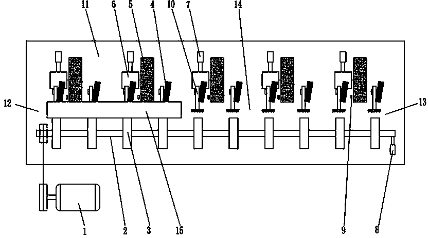
[0010] Such as figure 1 As shown, the present invention discloses a shaft polishing machine, which includes a workbench 11. The innovation point is mainly that a main shaft 2 is connected to the workbench 11, and the main shaft 2 is connected to the main motor 1 through transmission. 2 is provided with several driving wheels 3, the main motor 1 can drive the main shaft 2 to rotate, and drive the driving wheels 3 to rotate at the same time; the workbench 11 is also fixed with several guide wheels 4, and the guide wheels 4 rotate respectively Connected on a guide wheel frame 10, the axis of the guide wheel 4 is at an angle to the axis of the main shaft 2, and all the guide wheels 4 are arranged in parallel with the main shaft 2 after being arranged in a row; the drive wheel 3 and the guide wheel 4 form a shaft placement space 14, that is, during specific work, the shaft 15 to be polished is placed in the shaft placement space 14 between the drive wheel 3 and the guide wheel 4, a...


PUM


Abstract

The invention discloses a polishing machine for a shaft. The polishing machine comprises a workbench, a main shaft is connected to the workbench, the main shaft is in transmission connection with a main motor, and a plurality of driving wheels are arranged on the main shaft. A plurality of guide wheels are fixed to the workbench, and the guide wheels are parallel to the main shaft. A plurality of polishing wheels in transmission connection with polishing motors respectively are arranged on the workbench, the polishing motors are in transmission connection with polishing wheel feeding air cylinders respectively, and the polishing wheels are parallel to the main shaft. According to the polishing machine for the shaft, the driving wheels and the guide wheels form a shaft moving channel, the shaft rolls and axially moves under the action of the driving wheels and the guide wheels, rough polishing, medium polishing and fine polishing are respectively completed in the rolling and axial moving process so that all the polishing can be completed with one-time mounting, convenience is achieved, and polishing quality is guaranteed.

Description

technical field [0001] The invention relates to a polishing machine, in particular to a polishing machine for automatically polishing the peripheral surface of shaft parts. Background technique [0002] For some shaft parts with high precision requirements, after the grinding process is completed, the peripheral surface needs to be polished to remove the tiny protrusions and depressions formed on the peripheral surface during the grinding process. For coarse polishing, medium polishing and fine polishing, polishing wheels with different thicknesses are used respectively. Existing ordinary shaft polishing machines often only have one polishing wheel. The operator performs rough polishing, medium polishing and fine polishing on the outer surface of the shaft by moving the polishing wheel. It is necessary to remove the shaft from the polishing machine, which not only reduces the production efficiency, but also easily causes scratches on the shaft surface. Contents of the inv...

Claims


Application Information

Patent Timeline
Patent Type & Authority Applications(China)
IPC IPC(8): B24B29/04
CPCB24B29/04B24B41/005
Inventor 阮海祥阮连娟
Owner ZHEJIANG TAISHAN HEAVY MACHINERY
Why Eureka
Try Eureka