Two-way pushing utility knife and its adjusting device

An adjustment device and utility knife technology, which is applied in metal processing and other directions, can solve the problems of lack of positioning blade function and complicated slider structure, and achieve the effects of improving aesthetics, increasing contact area and pushing force, and increasing length

Active Publication Date: 2016-01-06
SDI CORPORATION
View PDF9 Cites 1 Cited by
  • Summary
  • Abstract
  • Description
  • Claims
  • Application Information

AI Technical Summary

Problems solved by technology

[0003] However, the upper adjuster of the existing adjustment device such as reference case 1 is generally flat, so it only has a single push surface, so it can only be pushed in one direction in a specific direction or in a gripping manner, which is inconvenient in use In addition, in accordance with the structure of the existing adjustment device, the chute on the existing utility knife holder is mostly set at the middle position on the side of the knife holder, and has a relatively large width, so that foreign objects can easily enter the interior of the knife holder and Affect the smoothness of utility knife operation
[0004] And China Taiwan's No. 281141 "Easy to disassemble and assemble so as to replace the utility knife structure of the blade" novel patent case (hereinafter referred to as reference case 2), it is provided with a push button, though this push button is L-shaped section, to provide two pushed It is provided for the user to push the push button in different directions, but the push button in reference case 2 is a single component structure and does not have the function of positioning the blade, so the user needs to continue to push the push button to make the blade move when cutting. Keeping it in the protruding position also has many inconveniences and restrictions in operation
[0005] In addition, Chinese Patent Publication No. 101269491 "Cutting Knife" Invention Disclosure (hereinafter referred to as reference case 3), the adjusting device of reference case 3 is a slider, but the structure of the slider in reference case 3 is relatively complicated, and it can only be Push operation in one direction, there is room for further improvement in use

Method used


Image

  • Two-way pushing utility knife and its adjusting device
  • Two-way pushing utility knife and its adjusting device
  • Two-way pushing utility knife and its adjusting device

Examples


Embodiment Construction

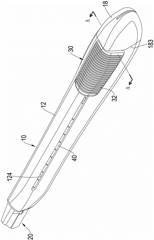
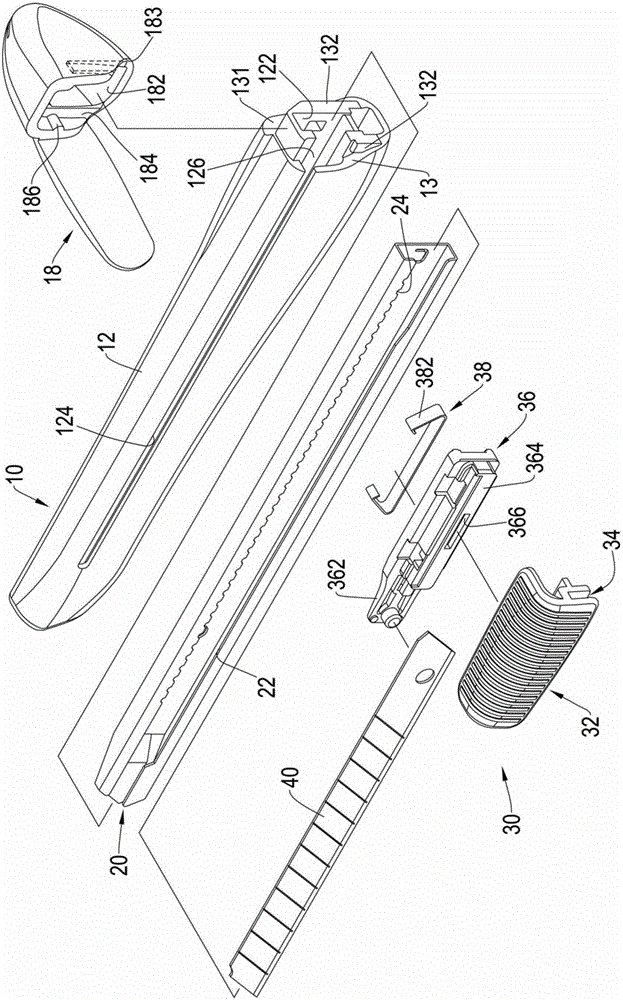
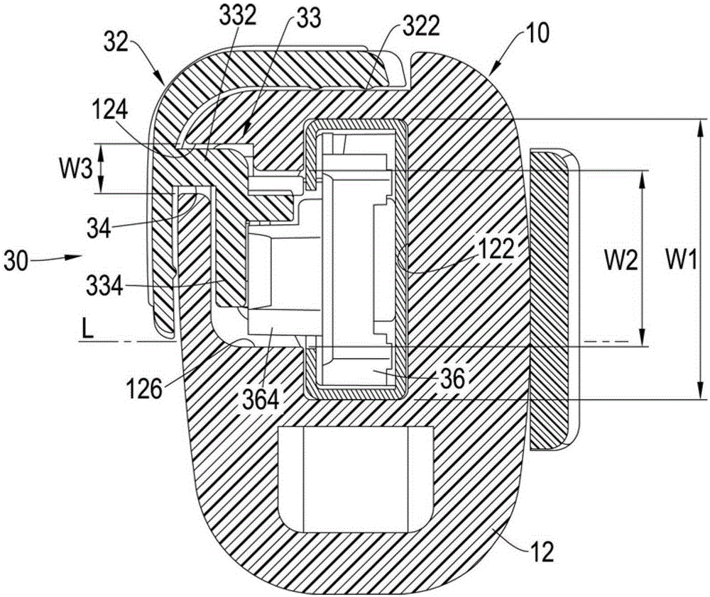
[0052] The invention provides a two-way pushing utility knife and its adjusting device, please refer to figure 1 , 2 , it can be seen from the figure that the utility knife of the present invention includes a casing 10, a knife holder 20, an adjusting device 30 and a blade 40, wherein the casing 10 can be made of plastic material, please refer to image 3 The housing 10 includes a hollow body 12 and a rear cover 18. An elongated chamber 122 extending longitudinally along the body 12 is formed in the body 12, and the front and rear ends of the body 12 are respectively formed to communicate with the chamber 122. Opening, and a long slide rail 124 extending longitudinally along the body 12 is provided on the side wall of the body 12. The slide rail 124 is arranged at a position above the center line L of the side wall of the body 12 and is close to the top of the body 12. On the surface, the center line L of the side wall refers to a line that roughly divides the side wall into ...


PUM


Abstract

The invention relates to a bidirectionally-pushed art knife and an adjusting device of the bidirectionally-pushed art knife. The bidirectionally-pushed art knife is provided with the adjusting device which is movably arranged on an outer shell and connected to a knife holder, and the adjusting device comprises an upper adjuster, a lower adjuster and an elastic sheet, wherein the lower adjuster is connected with the upper adjuster, and the elastic sheet is arranged on the lower adjuster to be capable of being buckled with a sawtooth part of the knife holder. The cross section of the upper adjuster is in an L shape, the upper adjuster is provided with a top face and a lateral wall, the top face and the lateral wall of the upper adjuster correspond to the body top face of the outer shell and the lateral wall, provided with a sliding rail, of a body of the outer shell respectively, a rail groove is formed in the upper adjuster, the part, forming the lateral edge face of the sliding rail, of the lateral wall of the body can be contained in the rail groove in a sliding mode, and the art knife convenient to operate is accordingly formed.

Description

technical field [0001] The invention relates to a utility knife and its adjusting device, in particular to a utility knife and its adjusting device which can be pushed in two directions. Background technique [0002] A utility knife is a common clerical tool used for cutting paper, etc. The existing utility knife is generally provided with an adjusting device on a knife seat that can move relative to the knife seat, and a blade can be moved by pushing the adjusting device. Push out or retreat into the knife seat, and position the blade at a predetermined extension length to meet the different cutting operation needs of the user. The existing utility knife is like the new patent case of "M390212 "Mei Knife Adjusting Device" in Taiwan, China (hereinafter referred to as reference case 1), the adjustment device of reference case 1 is slidably arranged in a knife seat and connected with a blade, the adjustment device mainly includes an upper regulator, a lower regulator and a shr...

Claims


Application Information

Patent Timeline
Patent Type & Authority Patents(China)
IPC IPC(8): B26B1/08
Inventor 许志玮
Owner SDI CORPORATION
Why Eureka
Try Eureka