Blocking mechanism of oil level indicator pipe

An oil dipstick and pipe sealing technology, which is applied to pipe components, mechanical equipment, pipes/pipe joints/fittings, etc., can solve the problems of troublesome sealing experiments, no blocking mechanism, and unsatisfactory results, and achieves convenient operation and blocking. The effect of tight and simple overall structure

Active Publication Date: 2014-03-12
通用技术集团大连机床有限责任公司
View PDF7 Cites 2 Cited by
  • Summary
  • Abstract
  • Description
  • Claims
  • Application Information

AI Technical Summary

Problems solved by technology

[0002] The gas sealing test of the inner cavity channel of the automobile engine is a key process of the engine body assembly production line. The oil dipstick tube must be blocked. At present, there is no good sealing mechanism, which brings trouble to the sealing test. In order to seal the oil dipstick tightly Pipeline operators used various methods to block, but the results were not ideal

Method used


Image

  • Blocking mechanism of oil level indicator pipe

Examples


Embodiment Construction

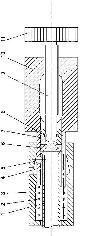
[0008] like figure 1 Shown: 1 is the oil dipstick tube of the car engine. The mechanism includes a front cover body 3 and a rear cover body 10 . The front part of the rear cover body 10 is inserted into the hole of the front cover body 1 , and a spring 2 is provided between the front end of the rear cover body 10 and the inner end surface of the front cover body 1 . , a ring groove 4 is processed on the inner side of the rear part of the front cover body 1, the ring groove 4 is located on the outer side of the front part of the rear cover body 10, the diameter of the ring groove 4 gradually decreases from the front end to the rear end, and there is a hole in the front part of the rear cover body 10 , the steel ball 5 is located in the hole, the inner hole of the rear sleeve body 10 is threadedly connected with a screw rod 9, the front end of the screw rod 9 is connected with a pressure head 7 through a snap ring 8, and the pressure head 7 is sleeved on the front end of the scr...


PUM


Abstract

The invention discloses a blocking mechanism of an oil level indicator pipe. The blocking mechanism comprises a front sleeve body and a back sleeve body, the front portion of the back sleeve body is inserted into a hole of the front sleeve body, a spring is arranged between the front end of the back sleeve body and the inner end face of the front sleeve body, an annular groove is arranged in the inner side of the back portion of the front sleeve body, the annular groove is located in the outer side of the front portion of the back sleeve body, the diameter of the annular groove is gradually changed smaller from the front end to the back end, a hole is formed in the front portion of the back sleeve body, a steel ball is located in the hole, a screw rod is connected with the inner hole of the back sleeve body in a threaded mode, a blocking ring is connected with the front end of the screw rod, and a hand wheel is connected with the rear end of the screw rod. The blocking mechanism is simple in overall structure, tight in blocking and convenient to operate.

Description

technical field [0001] The invention relates to a plugging mechanism for an oil dipstick tube, which is used for plugging an oil dipstick tube of an automobile engine. Background technique [0002] The gas sealing test of the inner cavity channel of the automobile engine is a key process of the engine body assembly production line. The oil dipstick tube must be blocked. There is no good blocking mechanism at present, which brings trouble to the sealing test. In order to tightly seal the oil dipstick Tube operators have used a variety of methods for plugging with unsatisfactory results. SUMMARY OF THE INVENTION [0003] The purpose of the present invention is to provide an oil dipstick tube plugging mechanism with simple structure, tight sealing and convenient operation, and overcome the deficiencies of the prior art. [0004] The oil dipstick tube plugging mechanism of the present invention includes a front cover body and a rear cover body, the front part of the rear cove...

Claims


Application Information

Patent Timeline
Patent Type & Authority Applications(China)
IPC IPC(8): F16L55/115
CPCF16L55/115
Inventor 祝恩临彭小敢张磊金明来
Owner 通用技术集团大连机床有限责任公司
Why Eureka
Try Eureka