
Plug connector and electric connector combination

A technology of plug connectors and electrical connectors, which is applied in the direction of connection, two-part connection devices, devices for joining/disconnecting connection parts, etc., and can solve the problem of loose fit between plug connectors and socket connectors, and easy left and right swings of plug connectors , Affect the electrical connection between the plug connector and the socket connector, etc., to achieve the effect of compact fit, guaranteed contact reliability, and stable electrical connection

Active Publication Date: 2014-03-12
LUXSHARE PRECISION INDKUNSHAN
View PDF10 Cites 7 Cited by
  • Summary
  • Abstract
  • Description
  • Claims
  • Application Information

AI Technical Summary

Problems solved by technology

[0004] When the plug connector is inserted into the socket connector forward, the tongue plate is accommodated in the slot, the conductive piece on the tongue plate and the contact part of the elastic terminal contact each other, and the positioning plate is supported upward on the bottom surface of the socket connector to play a supporting role. With the function of guiding, the locking arm and the locking block are locked together to limit the front and rear disengagement of the plug connector and the socket connector. However, in the left and right directions, the plug connector and the socket connector are relatively loose and loose, resulting in the plug connection The connector is easy to swing left and right, which affects the contact reliability between the conductive sheet on the tongue plate and the elastic terminal, thus affecting the electrical connection between the plug connector and the socket connector

Method used


Image

  • Plug connector and electric connector combination
  • Plug connector and electric connector combination
  • Plug connector and electric connector combination

Examples


Embodiment Construction

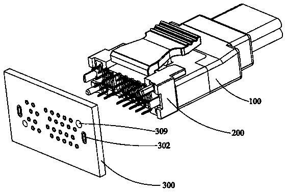
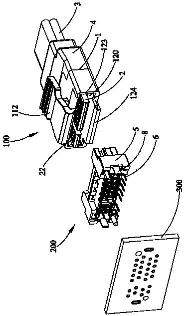
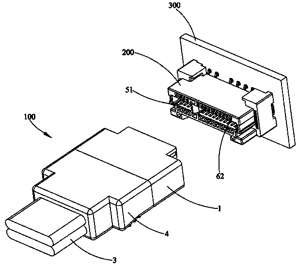
[0020] see Figure 1 to Figure 10 As shown, the present invention provides an electrical connector combination, which conforms to the USB 3.0 protocol, and the electrical connector combination includes a plug connector 100 and a socket connector 200 that are mated to each other, and the socket connector 200 is used for soldering to the mother circuit board 300 on.

[0021] The plug connector 100 conforms to the USB 3.0 protocol, which includes a plug body 1 made of insulating material, a sub-circuit board 2 located in the plug body 1, a cable 3 electrically connected to the sub-circuit board 2 and a plug body wrapped in the plug body. 1 the insulating shell 4 between the rear end and the front end of the cable 3 .

[0022] The plug body 1 includes a main body 11 and a square frame body 12 protruding forward from the main body 11. The main body 11 has a mating surface 111 at the front end, and the frame body 12 includes a The top wall 121, the bottom wall 122, the two side wa...


PUM


Abstract

The invention provides an electric connector combination which comprises a plug connector and a socket connector, wherein the plug connector and the socket connector are in butt joint. The plug connector comprises a plug body, a sub circuit board which is accommodated in the plug body and a cable which is electrically connected with the sub circuit board. The plug body has a matching surface. The sub circuit board has a tongue board which protrudes out of the matching surface toward the socket connector and a number of conductive films which are arranged on the surface of the tongue board. The socket connector comprises a socket body and a number of elastic terminals which are accommodated in the socket body. The socket body has a butt joint part and an insertion slot which is concavely arranged on the butt joint part to accommodate the tongue board. The plug body has two side walls which protrude from the matching surface toward the socket connector and are located on left and right sides of the tongue board. Two side walls are located on left and right sides of the butt joint part to limit left and right swinging of the plug connector.

Description

technical field [0001] The invention relates to a plug connector and an electrical connector combination, in particular to a plug connector and an electrical connector combination for transmitting high-frequency signals. Background technique [0002] Universal Serial Bus (USB) has been widely used in various electronic products. Jointly formulated by International Business Machines Corporation), Microsoft (Microsoft), and Northern Telecom (Northern Telecom Corporation), it has developed from USB 2.0 to USB 3.0. USB 3.0 has ten times the transmission speed of USB 2.0 and higher energy-saving efficiency. In the future, Will be more widely used in PC peripherals and consumer electronics. [0003] For the prior art related to this case, please refer to the electrical connector combination disclosed in the Chinese patent CN 202159800U announced on March 7, 2012. It includes a plug body and a sub-circuit board located in the plug body. The plug body is provided with a mating sur...

Claims


Application Information

Patent Timeline
Patent Type & Authority Applications(China)
IPC IPC(8): H01R13/62H01R13/46H01R24/00
Inventor 吴林戈明冯韶凌
Owner LUXSHARE PRECISION INDKUNSHAN
Learn More