Vapor heat exchanger system with water drainage function
A heat exchanger and steam technology, used in heat exchange equipment, lighting and heating equipment, deicing and other directions, can solve the problem of condensed water at the bottom of U-shaped, and achieve the effect of improving heat exchange capacity
Inactive Publication Date: 2014-03-19
YUNNAN FENG PU TECH
View PDF8 Cites 0 Cited by
- Summary
- Abstract
- Description
- Claims
- Application Information
AI Technical Summary
Problems solved by technology
[0003] For the existing steam heat exchanger system, the steam heat exchanger works under the design conditions. When the steam heat exchanger has a U-shaped structure at the steam inlet or in the heat exchanger, condensed water will be generated at the bottom of the U-shaped
Method used
View moreImage
Smart ImageViewing Examples

Examples
Embodiment Construction
[0008] The following is a further description in conjunction with the embodiments of the present invention and the drawings.
[0009] Implement one
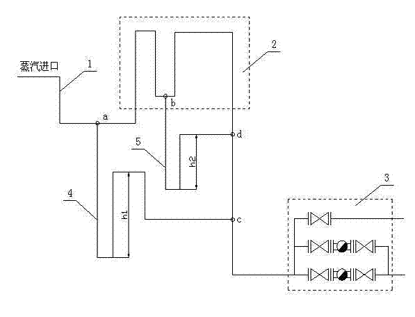
[0010] Such as figure 1 As shown, the steam heat exchanger system includes a steam inlet pipe 1, a steam heat exchanger 2, an automatic drain valve group 3, and also includes newly added automatic drain pipes 4 and 5. When the steam heat exchanger system is working, the condensate at point a in the steam inlet pipe 1 is discharged through the automatic drain pipe 4, and the condensate at point b in the steam heat exchanger 2 is discharged through the automatic drain pipe 5.
Login to View More PUM
 Abstract
The invention provides a water drainage system which can adjust condensation water at the U-type bottom of a vapor pipe according to vapor flow resistance of a vapor heat exchanger and improve heat exchange efficiency of the vapor heat exchanger on the condition that an automatic water drainage valve block is not additionally provided when the heat exchanger with vapor as a heat source is used and a U-type structure is inevitably formed due to structure limits of the heat exchanger, and particularly relates to a vapor heat exchanger system with a water drainage function. The system comprises components of a traditional vapor heat exchanger system and is further additionally provided with an automatic water drainage pipe for condensation water at the U-type bottom of the heat exchanger, and the automatic water drainage pipe can be used for discharging the condensation water at the U-type bottom of the heat exchanger.
Description
Technical field [0001] The invention is a system involving a steam heat exchanger. Background technique [0002] At present, the steam heat exchanger using steam as the heat source is widely used. Under normal circumstances, the steam heat exchanger works under the design conditions. It can make full use of the latent heat of vaporization of steam for heat exchange. It is a kind of fully utilized steam enthalpy. the way. However, due to the structural limitation of the heat exchanger, sometimes a U-shaped structure appears at the steam inlet or in the heat exchanger. At this time, condensate will be generated at the bottom of the U-shaped, and the condensed water at the bottom of the U-shaped will not be discharged in time, which will affect The heat exchange efficiency of the steam heat exchanger. We can install an automatic trap at the bottom of the U-shape to drain, but doing so will increase the cost and maintenance points. Summary of the invention [0003] For the existing...
Claims
Login to View More Application Information
Patent Timeline
 IPC IPC(8): F28F17/00
Inventor 王永胜袁江朱鸿野赵铁王宇李慧歆
Owner YUNNAN FENG PU TECH