Injection enhancement radiator

A radiator and heat-dissipating substrate technology, applied in cooling/ventilation/heating transformation, electrical components, electrical equipment structural parts, etc., can solve the problems of blocked coolant flow, increased pressure loss, increased processing difficulty, etc. Eliminate flow resistance restrictions, increase heat transfer capacity, and reduce processing costs

Active Publication Date: 2020-05-08
JIHUA LAB
View PDF6 Cites 2 Cited by
  • Summary
  • Abstract
  • Description
  • Claims
  • Application Information

AI Technical Summary

Problems solved by technology

This type of design generally causes the following problems: due to the sharp increase in the heat flux density of the heating element, the radiator will also be forced to seek a larger heat dissipation area to meet the heat dissipation requirements, which will inevitably increase the number of fins, increase the length of the

Method used


Image

  • Injection enhancement radiator
  • Injection enhancement radiator
  • Injection enhancement radiator

Examples


Example Embodiment

[0024] Embodiments of the present invention are described in detail below, examples of which are shown in the drawings, wherein the same or similar reference numerals denote the same or similar elements or elements having the same or similar functions throughout. The embodiments described below by referring to the figures are exemplary only for explaining the present invention and should not be construed as limiting the present invention.

[0025] In describing the present invention, it should be understood that the terms "center", "longitudinal", "transverse", "length", "width", "thickness", "upper", "lower", "front", " Orientation indicated by rear, left, right, vertical, horizontal, top, bottom, inside, outside, clockwise, counterclockwise, etc. The positional relationship is based on the orientation or positional relationship shown in the drawings, which is only for the convenience of describing the present invention and simplifying the description, rather than indicating ...


PUM


Abstract

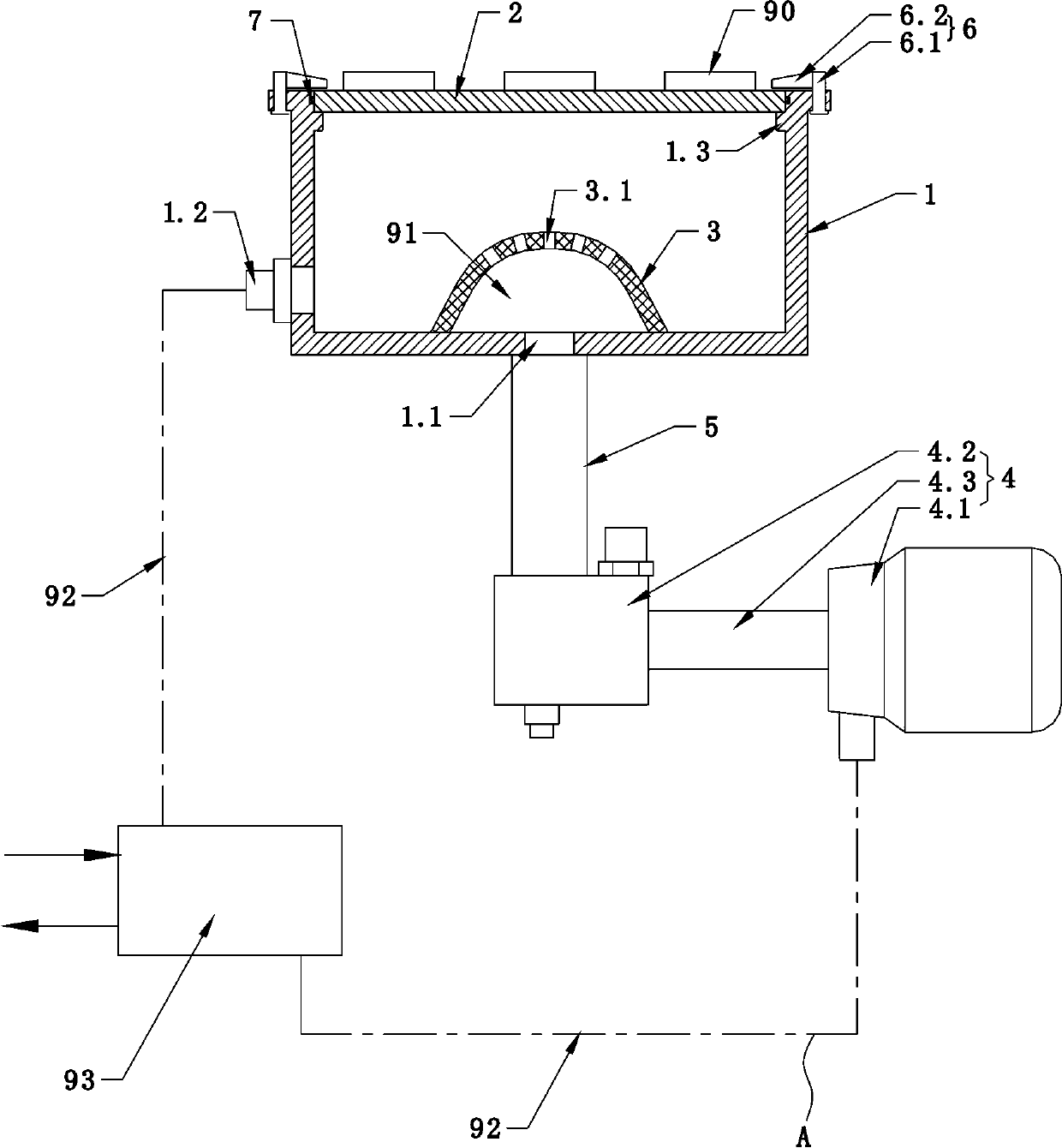
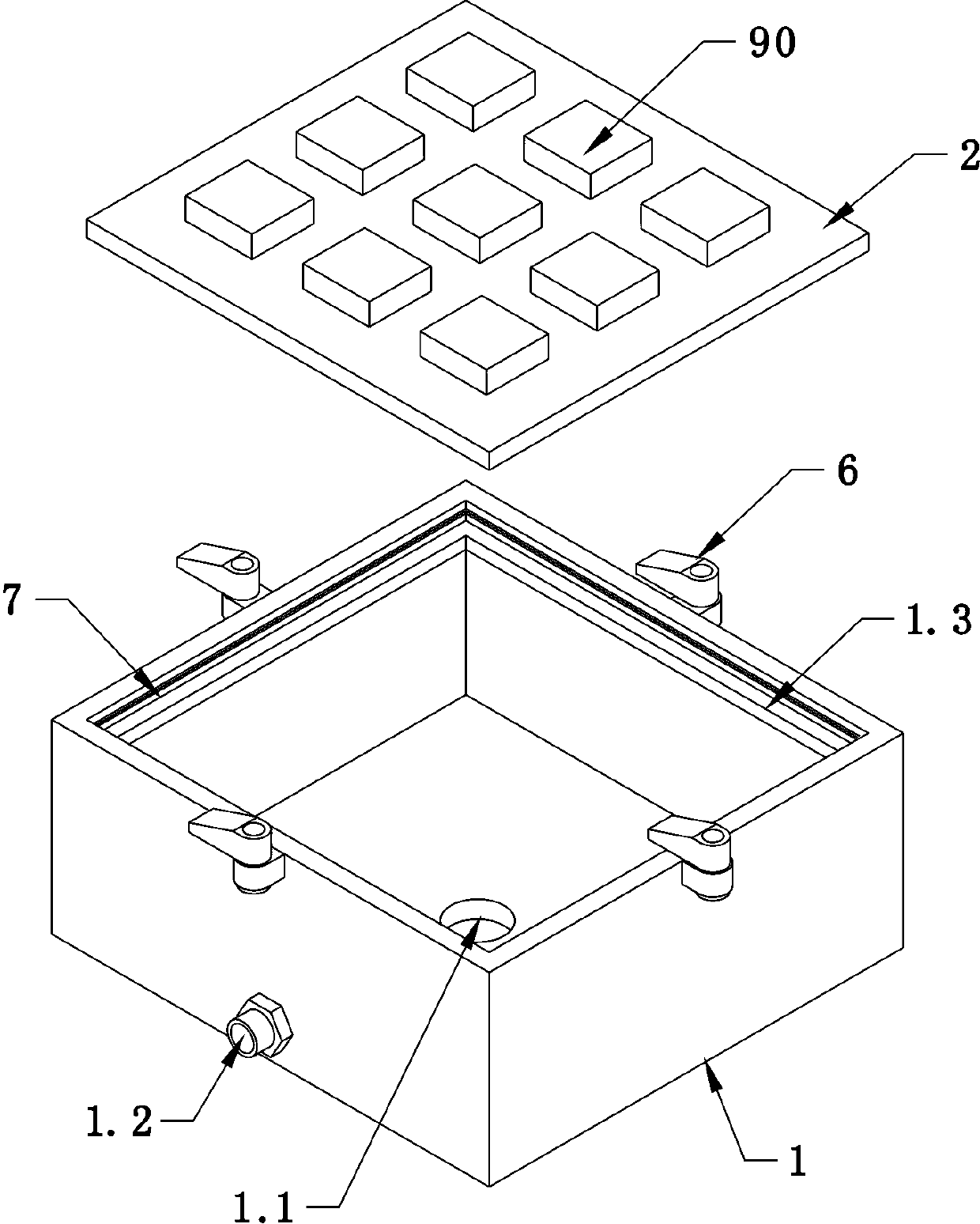
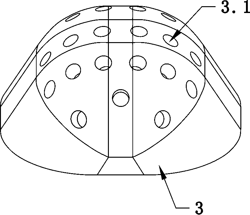
The invention provides an injection enhancement radiator. The radiator comprises an injection control cavity with an opening in the upper side, a heat dissipation substrate covering the opening in theupper side of the injection control cavity, an injection device arranged on the lower portion in the injection control cavity, and a high-pressure conveying device used for conveying high-pressure cooling liquid to the injection device; a spraying device which is used for spraying high-pressure cooling liquid upwards to form high-pressure spray, wherein the upper surface of the heat dissipation substrate is used for arranging a heating element. The radiator can effectively dissipate heat of a high-flow-density heating element, and is simple in structure, low in manufacturing difficulty and low in machining cost.

Description

technical field [0001] The invention relates to the technical field of radiators, in particular to a spray-enhanced radiator. Background technique [0002] At present, high-power electronic equipment components typically represented by supercomputing CPUs or high-power power supply IGBT components have shown a polarized trend of maximizing power loads and minimizing component sizes. The performance of various electronic components in electronic equipment Getting stronger and stronger. At the same time, within the limited volume space, the integration density of these electronic components in the equipment or in the PCB board is getting higher and higher. In the future, the power of these high-precision, high-power devices will continue to increase, the heat consumption of the entire device will also range from tens of kilowatts to megawatts, and the heat generation of its core electronic components will also range from several thousand watts to tens of kilowatts. Wait. Th...

Claims


Application Information

Patent Timeline
IPC IPC(8): H05K7/20
CPCH05K7/20272
Inventor 黄星星胡强侯立涛徐平胡琅冯杰黎天韵尤晶
Owner JIHUA LAB
Why Eureka
Try Eureka