Heating cooker

A cooker and heater technology, which is applied in the directions of heating method, electric heating fuel, lighting and heating equipment, etc., can solve the problems such as the decrease of fan air supply performance, the increase of fan size, and the thinning of the cooker that cannot be heated, and achieves good performance. The effect of air supply performance, thin axial thickness of the fan, and good air supply performance of the fan

Inactive Publication Date: 2014-03-19
SHARP KK
View PDF7 Cites 65 Cited by
  • Summary
  • Abstract
  • Description
  • Claims
  • Application Information

AI Technical Summary

Problems solved by technology

[0004] In the above-mentioned conventional heating cooker, if the thickness of the above-mentioned blades is reduced in order to reduce the thickness of the heating cooker, the air blowing performance of the fan is reduced, and there is a problem that the heat exchange of the heat medium cannot be performed efficiently.
In addition, on the contrary, if the thickness of the above-mentioned blades is increased in order to improve the air blowing performance of the fan, the axial dimension of the fan becomes large, and there is a problem that the heating cooker cannot be thinned.

Method used


Image

  • Heating cooker
  • Heating cooker
  • Heating cooker

Examples


Embodiment Construction

[0051] Hereinafter, the present invention will be described in detail using illustrations.

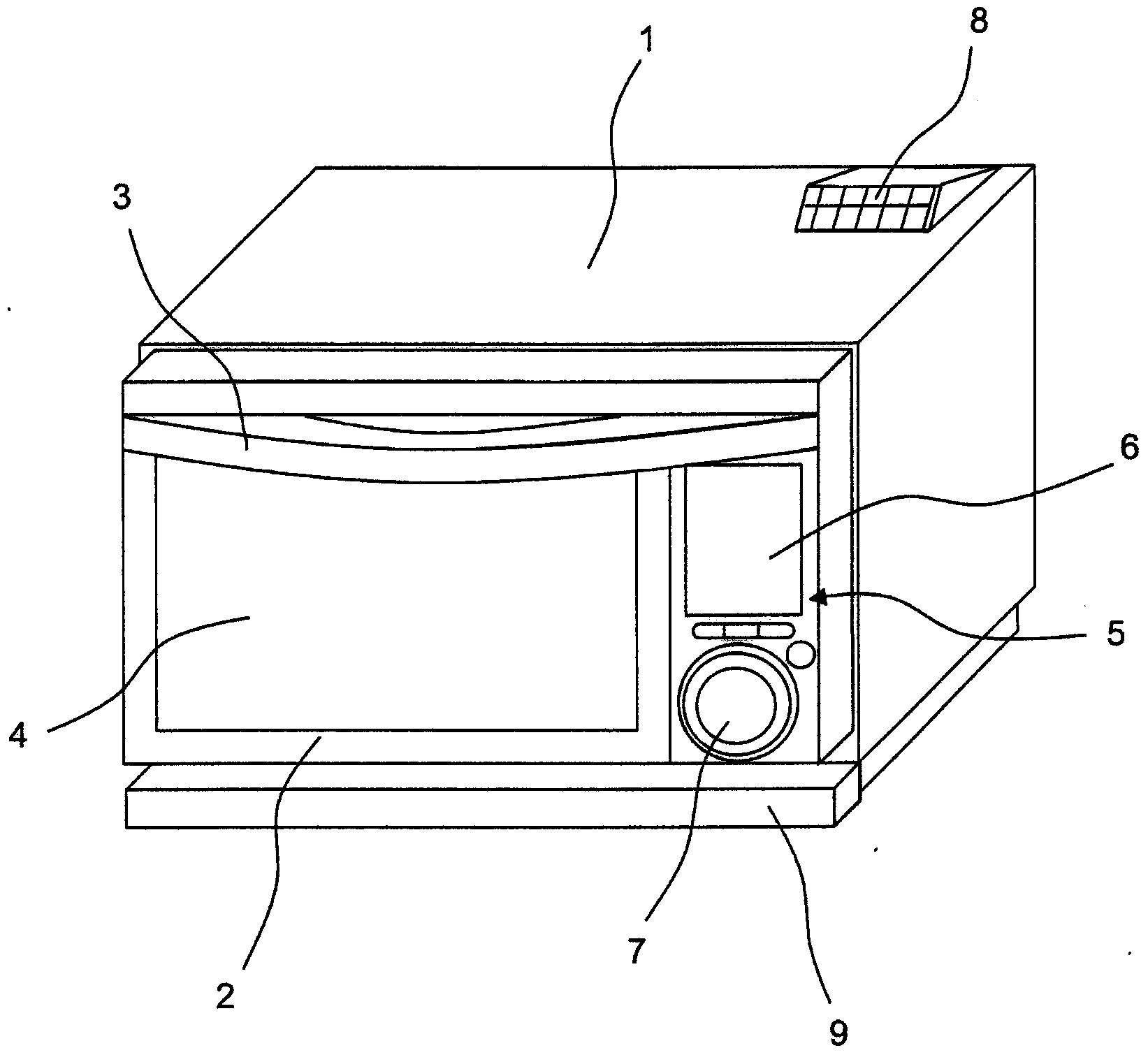
[0052] figure 1 It is a perspective view of the heating cooker which concerns on one Embodiment of this invention.

[0053] Such as figure 1 As shown, the above-mentioned heating cooker is equipped with a door 2 on the front surface of a rectangular parallelepiped casing 1, and the door 2 is rotated substantially around the side on the lower end side. A handle 3 is attached to the upper portion of the door 2 , and a heat-resistant glass 4 is attached to the approximate center of the door 2 . Furthermore, an operation panel 5 is provided on the right side of the door 2 . The operation panel 5 has a liquid crystal display 6 and knobs 7 . In addition, an exhaust port 8 is provided on the upper side and right rear of the housing 1 . In addition, a dew-receiving container 9 is installed under the door 2 of the casing 1 .

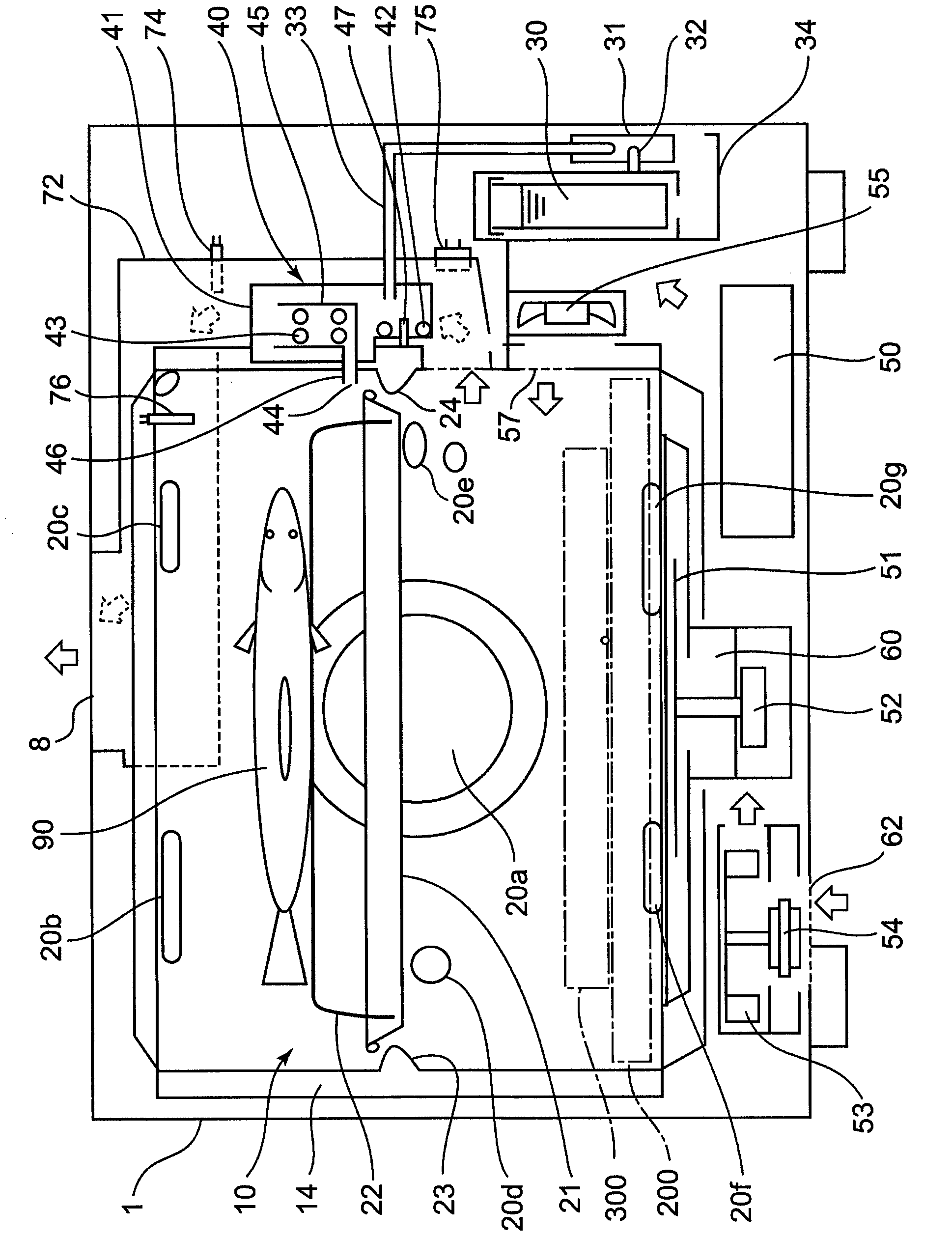
[0054] figure 2It is a cross-sectional schematic view seen f...


PUM


Abstract

A convection fan (410) is installed at an end surface (436) of a circular truncated cone-shaped projecting portion (430) projecting from the plate portion (420) of a convection fan duct (401). A portion (460) folded back toward the rear side is formed on the convection fan (410). The portion (460) is positioned on the side of the plate portion (420) of the convection fan duct (401) with respect to the end surface (436) of the circular truncated cone-shaped projecting portion (430) and is positioned laterally to the circular truncated cone-shaped projecting portion (430).

Description

technical field [0001] The present invention relates to a heating cooker. Background technique [0002] Conventionally, a heating cooker is described in Unexamined-Japanese-Patent No. 2009-24914 (patent document 1). The above-mentioned heating cooker is provided with a fan behind the fan duct located at the rear side of the main body casing, and the heat medium in the heating chamber is sucked in by the fan from the suction port of the heating chamber and blown out radially to perform heat exchange with the heat medium. [0003] The fan includes a fan body and a blade protruding from a surface of the fan on the heating chamber side toward the fan axial direction toward the heating chamber. In the above-mentioned conventional heating cooker, the flow of the heat medium is restricted by the fins protruding toward the heating chamber, and the heat medium is blown out on the same plane as the flat surface of the fan, or on the side closer to the heating chamber than the above-m...

Claims


Application Information

Patent Timeline
Patent Type & Authority Applications(China)
IPC IPC(8): F24C1/00
CPCF24C1/00F24C15/325F24C7/06
Inventor 西岛正浩岸本卓士松林一之
Owner SHARP KK
Why Eureka
Try Eureka