Method for operating a thermodynamic cycle, and thermodynamic cycle

A cyclic operation, thermal power technology, applied in machine/engine, steam engine installation, combined combustion mitigation, etc., can solve problems such as pressure pulsation, emergency cycle interruption, etc.

Active Publication Date: 2011-06-01
KALINA POWER LTD
View PDF6 Cites 11 Cited by
  • Summary
  • Abstract
  • Description
  • Claims
  • Application Information

AI Technical Summary

Problems solved by technology

But if this principle were applied in the Kalina cycle described above, during the initiation of the cycle it could lead to pressure pulses in the cycle which could be so large as to necessitate an emergency interruption of the cycle

Method used


Image

  • Method for operating a thermodynamic cycle, and thermodynamic cycle
  • Method for operating a thermodynamic cycle, and thermodynamic cycle

Examples


Embodiment Construction

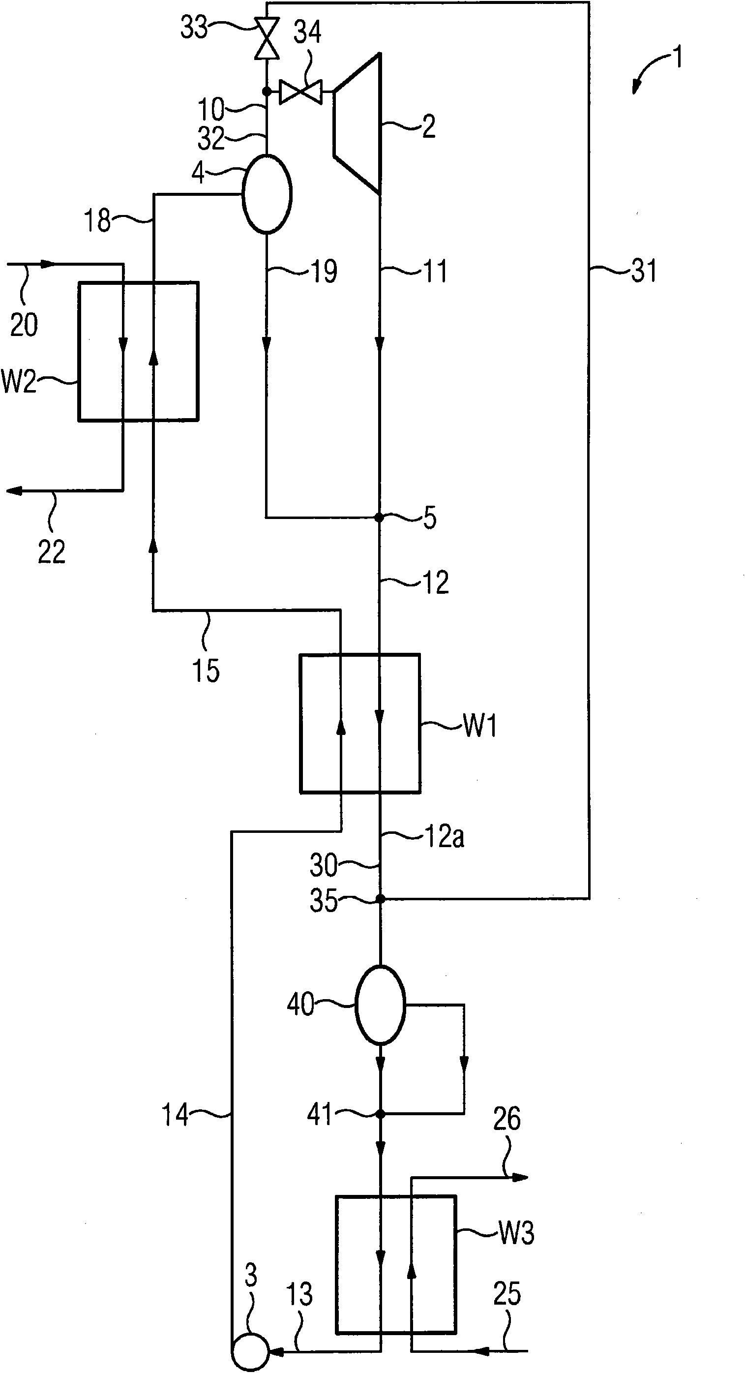
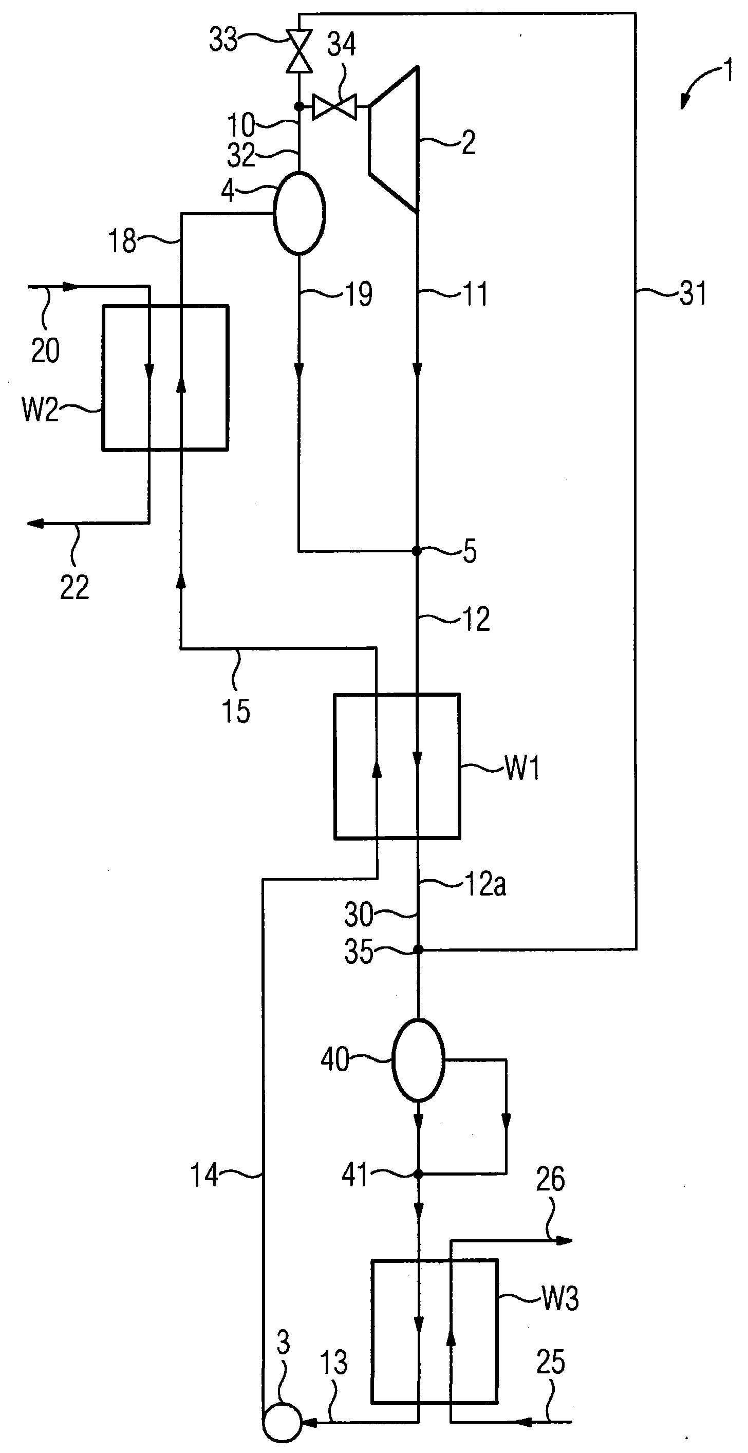
[0019] The thermodynamic cycle 1 shown in the drawings includes a first heat exchanger (preheater) W1, a second heat exchanger (evaporator) W2 and a third heat exchanger (condenser) W3.

[0020] The second heat exchanger W2 is in thermal contact with an external heat source on the primary side, in the illustrated embodiment the second heat exchanger is circulated on the primary side by hot water 20 from an earth heat source not shown in detail, and on the secondary side The stage side is connected on the one hand to the first heat exchanger W1 and on the other hand to the separator 4 . The separator 4 serves to separate the vapor phase of the partially evaporated working medium from the liquid phase. The evaporation side outlet of the separator 4 is connected to the turbine 2 as an expansion device. The turbine 2 is connected on the outlet side to a collecting device in the form of a mixer 5 . The mixer 5 is additionally connected to the liquid outlet of the separator 4 . O...


PUM


Abstract

The invention relates to a thermodynamic cycle (1) with at least: - one first heat exchanger (W1) for creating a first heated or partially evaporated working medium flow (15) by heating or partially evaporating a liquid working medium flow (14) by heat transmission from an expanded working medium flow (12); - a second heat exchanger (W2) for creating a second at least partially evaporated working medium flow (18); - a separator (4) for separating a liquid phase (19) from a vaporous phase (10) of the second working medium flow (18); - an expansion device (2) for creating an expanded vaporous phase (10). According to the invention, pressure pulsations are prevented during the start-up of the cycle in that the vaporous phase (10) separated by the separator (4) is conducted past the expansion device (2) and the first heat exchanger (W1). The liquid phase (19) separated by the separator (4) is cooled in the first heat exchanger (W1) by heat transfer to the liquid working medium flow (14). After the first heat exchanger (W1), the cooled, separated, liquid phase and the separated vaporous phase (10) are brought together.

Description

technical field [0001] The invention relates to a method for operating a thermodynamic cycle according to the preamble of claim 1 and a thermodynamic cycle according to the preamble of claim 7; such a cycle is disclosed for example by EP1613841B1. Background technique [0002] Thermal power plants convert thermal energy into mechanical or electrical energy using a thermodynamic cycle process. Conventional thermal power plants generate heat by burning fuels, mainly fossil energy carriers coal, oil and natural gas. In this case, the cycle is operated, for example, on the basis of a conventional Rankine cycle with water as the working medium. But the high boiling point of water makes water unattractive due to low economics mainly when using heat sources with temperatures between 100 and 200° C., such as geothermal fluids or waste heat from combustion processes. [0003] In recent years, different theories have been developed for such low-temperature heat sources, which enable...

Claims


Application Information

Patent Timeline
Patent Type & Authority Applications(China)
IPC IPC(8): F01K25/06
CPCY02E20/14F01K25/065
Inventor J·伦格特M·伦格特R·卢茨
Owner KALINA POWER LTD
Why Eureka
Try Eureka