
Umbrella

An umbrella surface and umbrella pole technology, applied in the umbrella field, can solve the problems of easy-to-wet clothes, single structure, difficult to dry, etc., and achieve the effects of easy portability, high practicability, and convenient use

Inactive Publication Date: 2014-03-26
徐燕英
View PDF4 Cites 1 Cited by
  • Summary
  • Abstract
  • Description
  • Claims
  • Application Information

AI Technical Summary

Problems solved by technology

However, the existing umbrellas on the market are only limited to a single structure, and do not substantially solve the demand for the changeability of the structure or style of the same umbrella.
When the umbrella in the prior art is driving in heavy rain, it is easy to wet the clothes, especially in winter, the clothes in winter are relatively heavy, and it is difficult to dry in rainy days after getting wet, which is particularly inconvenient

Method used


Image

  • Umbrella
  • Umbrella

Examples


Embodiment 1

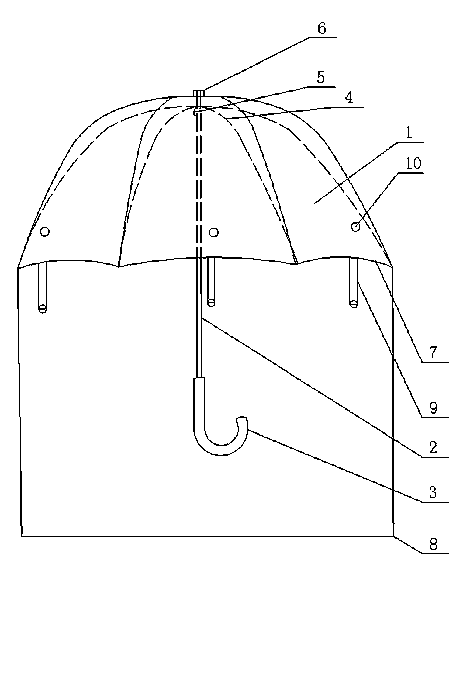
[0015] Such as figure 1 As shown, an umbrella of the present invention includes an umbrella surface 1, an umbrella shaft 2 and an umbrella handle 3. The umbrella surface 1 is movably fixed on the top of the umbrella shaft 2, and the umbrella handle 3 is fixed on the bottom of the umbrella shaft 2. The umbrella surface 1 is movably fixed on the umbrella pole 2 with a support frame 4 made of alloy, the umbrella pole 2 is provided with a fixing buckle 5, the top of the umbrella pole 2 is provided with a compression nut 6, and the umbrella surface 1 It is fixed by a compression nut 6 and a fixed buckle 5. A shield 8 is provided on the umbrella surface edge 7 around the umbrella surface 1 and a fixed buckle 9 is provided on the inner side of the bottom shield 8 of the umbrella surface edge 7. The outer side of the umbrella surface 1 is provided with a fixed base 10, the fixed buckle 9 and the fixed base 10 cooperate with each other, the protective cover 8 is made of transparent mater...

Embodiment 2

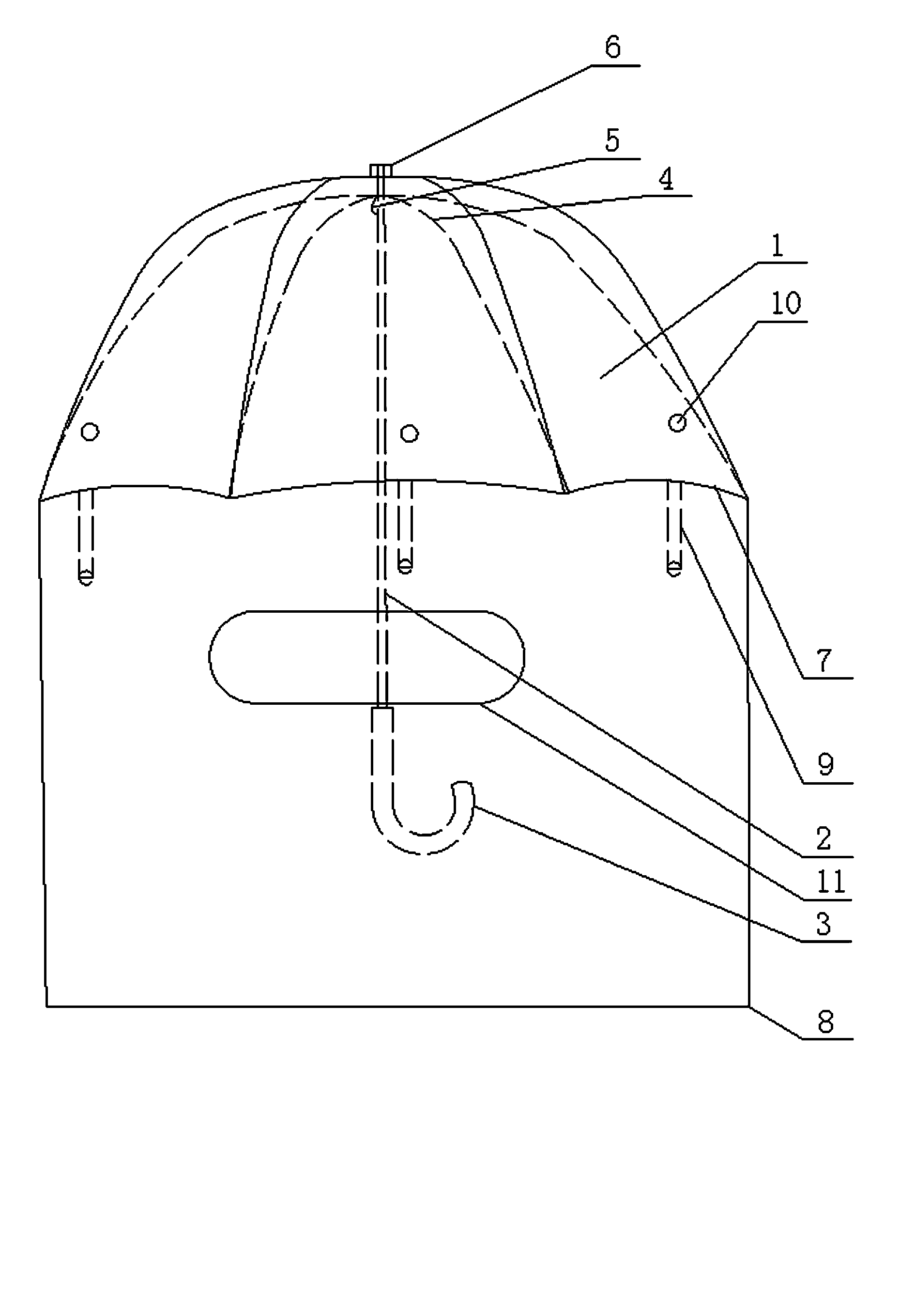
[0017] Such as figure 2 As shown, an umbrella of the present invention includes an umbrella surface 1, an umbrella shaft 2 and an umbrella handle 3. The umbrella surface 1 is movably fixed to the top of the umbrella shaft 2, and the umbrella shaft 3 is fixed to the bottom of the umbrella shaft 2. The umbrella surface 1 is movably fixed on the umbrella pole 2 with a support frame 4 made of alloy, the umbrella pole 2 is provided with a fixing buckle 5, the top of the umbrella pole 2 is provided with a compression nut 6, and the umbrella surface 1 It is fixed by a compression nut 6 and a fixed buckle 5. A shield 8 is provided on the umbrella surface edge 7 around the umbrella surface 1 and a fixed buckle 9 is provided on the inner side of the bottom shield 8 of the umbrella surface edge 7. The outer side of the umbrella surface 1 is provided with a fixed base 10, the fixed buckle 9 and the fixed base 10 cooperate with each other, the protective cover 8 is made of opaque material,...


PUM


Abstract

The invention discloses an umbrella. The umbrella comprises an umbrella cover, an umbrella rod and an umbrella handle. The umbrella cover is movably fixed on the top of the umbrella rod, and the umbrella handle is fixed to the bottom of the umbrella rod. The umbrella is characterized in that the umbrella cover is movably fixed on the umbrella rod through a supporting framework made of alloy, a fixing buckle is arranged on the umbrella rod, the top of the umbrella rod is provided with a pressing nut, the umbrella cover is fixed through the pressing nut and the fixing buckle, the peripheral edge of the umbrella cover is provided with a protection cover, the inner side of the protection cover of the bottom of the umbrella cover is provided with a fixing hasp, a fixing base is arranged on the outer side of the umbrella cover, the fixing hasp is matched with the fixing base, and the protection cover is made of transparent materials. The umbrella has the advantages that when a user walks in the heavy rain, the umbrella can prevent rainwater from wetting clothes, the overall structure is simple and decent, the umbrella is convenient to use and carry, convenience is brought to the user, and the umbrella has high practicality.

Description

Technical field [0001] The present invention relates to umbrellas, in particular to an umbrella. Background technique [0002] With the improvement of people's living standards, people's needs for various daily necessities are becoming more and more diversified. Take umbrellas as an example. Umbrellas are a tool to provide a cool environment or shelter from rain and snow. Therefore, people have more and more requirements for the style and color of umbrellas, and new requirements have been put forward for the variability of the structure or style of the same umbrella. However, the existing umbrellas on the market are limited to a single structure, and do not substantially meet the requirements of the same umbrella structure or style. Umbrellas in the prior art tend to get wet clothes when driving in heavy rain, especially in winter. Winter clothes are relatively heavy and difficult to dry in rainy days after getting wet, which is particularly inconvenient. [0003] Therefore, an i...

Claims


Application Information

Patent Timeline
Patent Type & Authority Applications(China)
IPC IPC(8): A45B25/18
Inventor 徐燕英
Owner 徐燕英
Learn More