
Boot frame structure

A boot rack and boot board technology can be applied to expandable cabinets, rotating cabinets, wardrobes, etc., which can solve problems such as difficult storage, moldy, and waste of boot space, so as to improve storage efficiency, improve structural strength, and solve space problems. wasteful effect

Inactive Publication Date: 2014-03-26
江俊毅
View PDF9 Cites 2 Cited by
  • Summary
  • Abstract
  • Description
  • Claims
  • Application Information

AI Technical Summary

Problems solved by technology

[0002] The known fixed shoe rack can only accommodate a small number of shoes, especially the space above the toe cap of high-heeled shoes is difficult to be utilized, resulting in waste of space, so a shoe rack with more space is available on the market, such as the Chinese Taiwan patent M433822 What is disclosed is a rotatable shoe rack with staggered inclined partitions. High-heeled shoes can be staggered and placed from opposite sides, so that the space can be effectively utilized and it is easy to access
[0003] However, the boots are difficult to store in the above-mentioned way due to their height. If they are forced to be inserted into the shoe rack of the above patent, the boots will be dented, which may have a bad effect on the appearance, and it is easier to accumulate moisture and become moldy. In general shoe cabinets, the space above the boot toe can no longer be stored, resulting in waste. Therefore, proper storage of boots to maintain a good appearance and save space usually cannot coexist

Method used


Image

  • Boot frame structure
  • Boot frame structure
  • Boot frame structure

Examples


Embodiment Construction

[0034] The following examples illustrate possible implementations of the present invention, but they are not intended to limit the protection scope of the present invention and are described in advance.

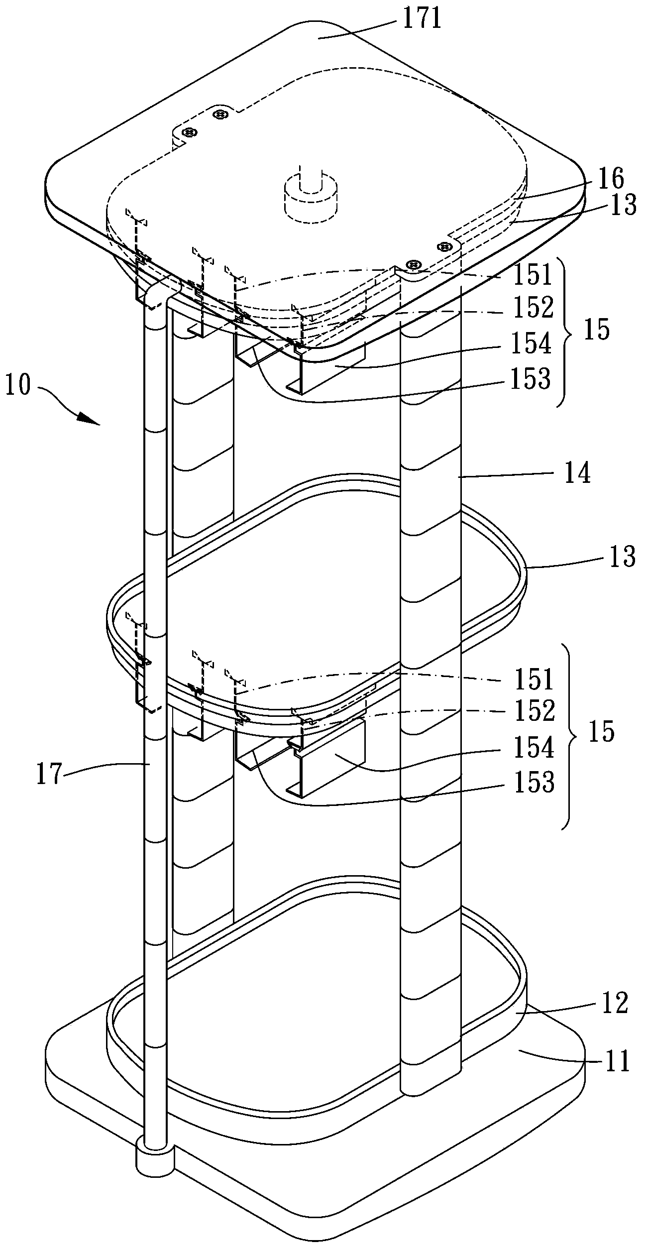
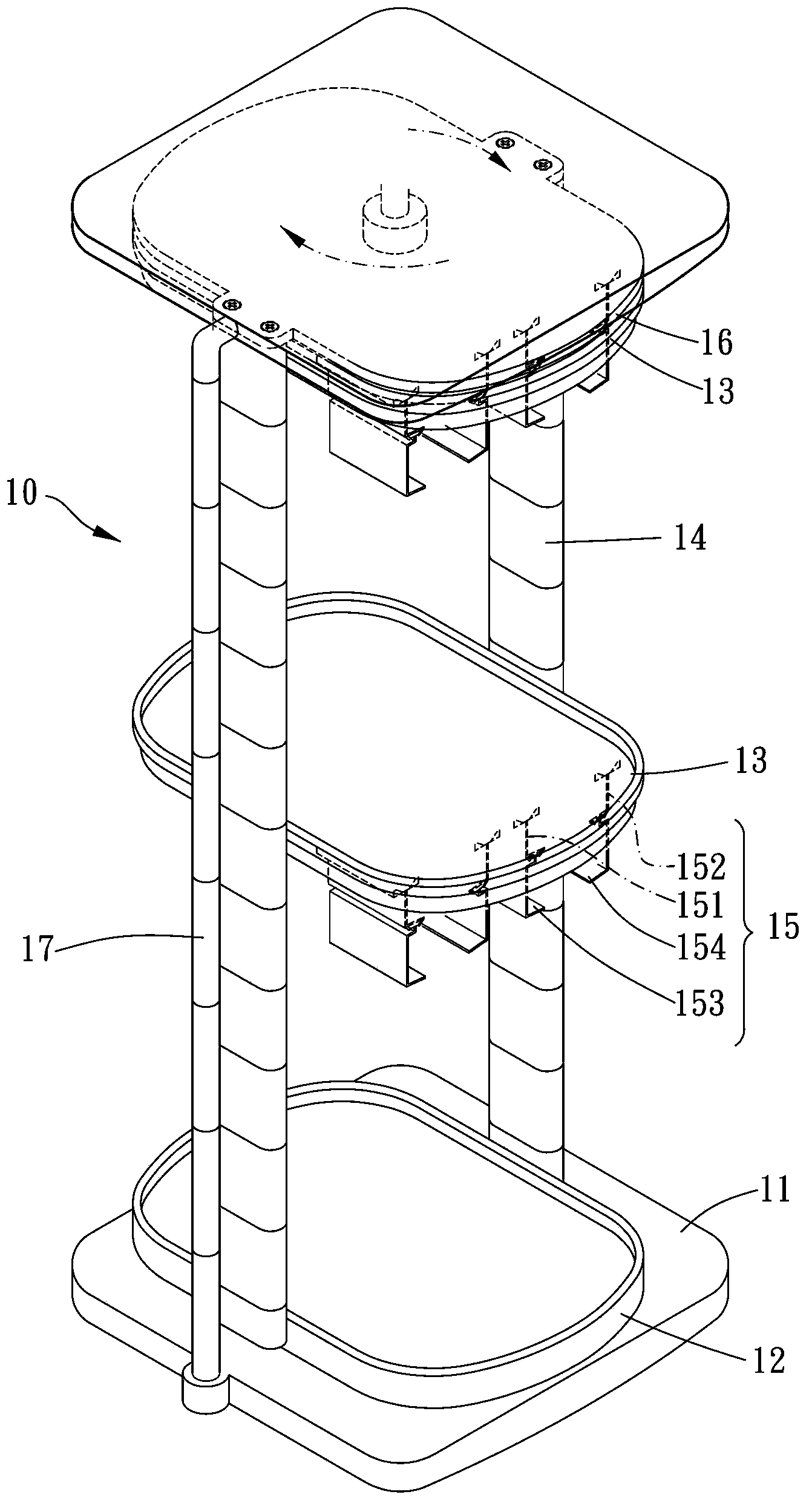
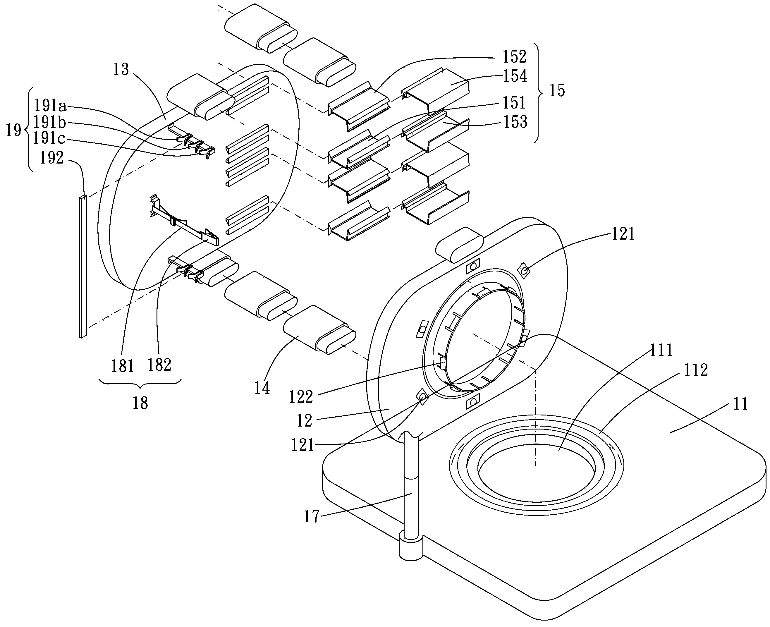
[0035] Please refer to figure 1 , figure 2 , image 3 , Figure 4 , Figure 5 , Figure 6 , Figure 7 , Figure 7A and Figure 8 , the shoe rack structure 10 includes a base 11, a chassis 12, at least one shoe plate 13, a plurality of assembly parts 14, at least one hanging part 15, a positioning part 19, a clamping part 18, a top plate 16. A reinforcing column 17 and a top cover 171 .

[0036] The chassis 12 is rotatably mounted on the base 11 . In the main embodiment of the present invention, the center of the base 11 is provided with a through hole 111, and the bottom of the chassis 12 protrudes to form a ring 122, and the ring 122 is rotatably arranged in the through hole 111, and the ring 122 can have a buckle structure and the through hole 111 is locked with ...


PUM


Abstract

The invention provides a boot frame structure. The structure comprises a base, a base plate, at least one boot holding plate, a plurality of assembly parts and at least one hanging part. The base plate is arranged on the base in a rotatable mode. The at least one boot holding plate is disposed on one side of the base plate, which is opposite to the base, and certain distance is left between the at least one boot holding plate and the base plate. The plurality of assembly parts are connected between the at least one boot holding plate and the base plate, and a boot holding space is defined by the plurality of assembly parts, the at least one boot holding plate and the base plate. The at least one hanging part extending towards the boot holding space from the bottoms of the at least one boot holding plate, and a hanging space is defined by the at least one hanging part and the at least one boot holding plate. Accordingly, boots can be put in the boot holding space with the boot soles downwards directly, or the boot soles are upward and boot heads are inserted in the hanging space, space is fully used, and an outstanding storage effect is obtained.

Description

technical field [0001] The invention relates to a boot rack. Background technique [0002] The known fixed shoe rack can only accommodate a small number of shoes, especially the space above the toe cap of high-heeled shoes is difficult to be utilized, resulting in waste of space, so a shoe rack with more space is available on the market, such as the Chinese Taiwan patent M433822 What is disclosed is a rotatable shoe rack with staggered inclined partitions, and high-heeled shoes can be placed staggered from opposite sides, so that the space can be effectively utilized and it is convenient to take. [0003] However, the boots are difficult to store in the above-mentioned way due to their height. If they are forced to be inserted into the shoe rack of the above patent, the boots will be dented, which may have a bad effect on the appearance, and it is easier to accumulate moisture and become moldy. In general shoe cabinets, the space above the toe of the boots can no longer be ...

Claims


Application Information

Patent Timeline
Patent Type & Authority Applications(China)
IPC IPC(8): A47B61/04A47B45/00A47B49/00
Inventor 江俊毅
Owner 江俊毅
Learn More